

Motor control system for endodontic handpiece providing dynamic torque limit tracking of specific file fatigue
- Summary
- Abstract
- Description
- Claims
- Application Information
AI Technical Summary
Benefits of technology
Problems solved by technology
Method used
Image

Examples
Embodiment Construction
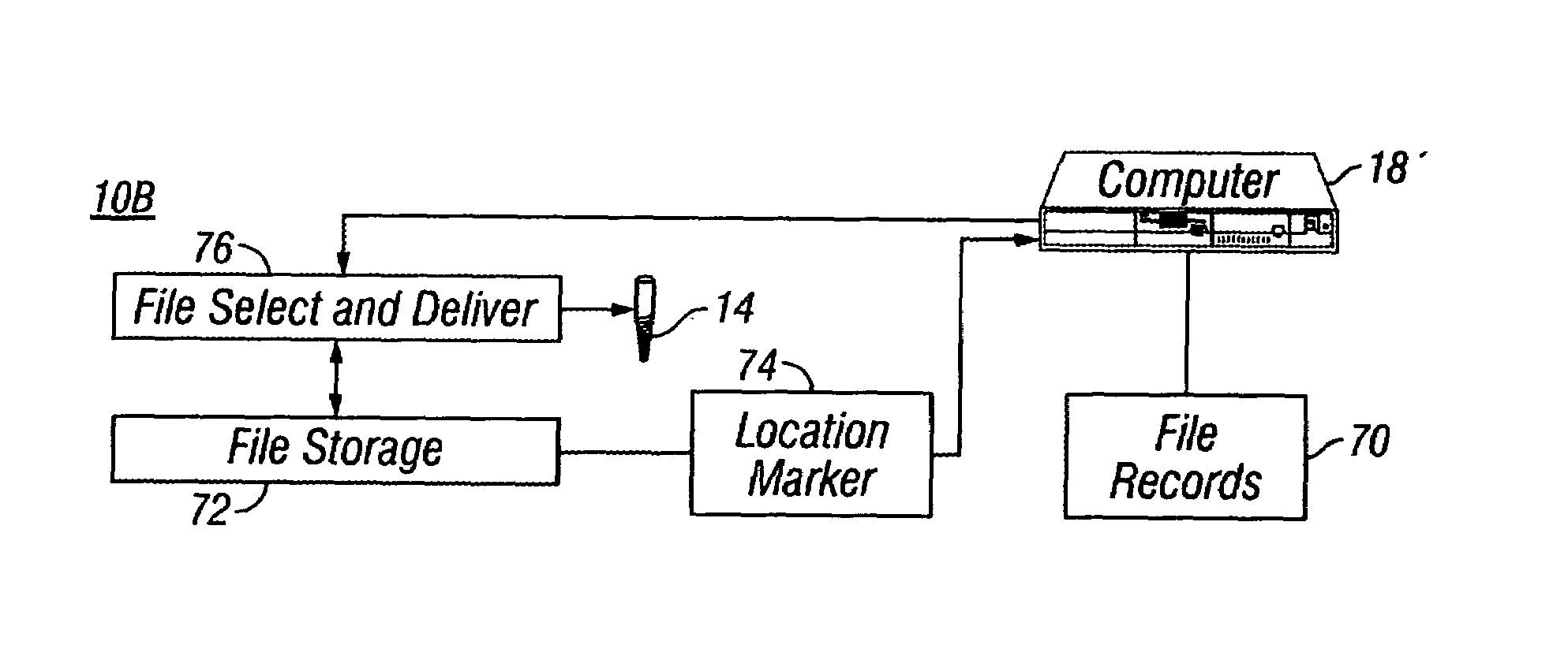
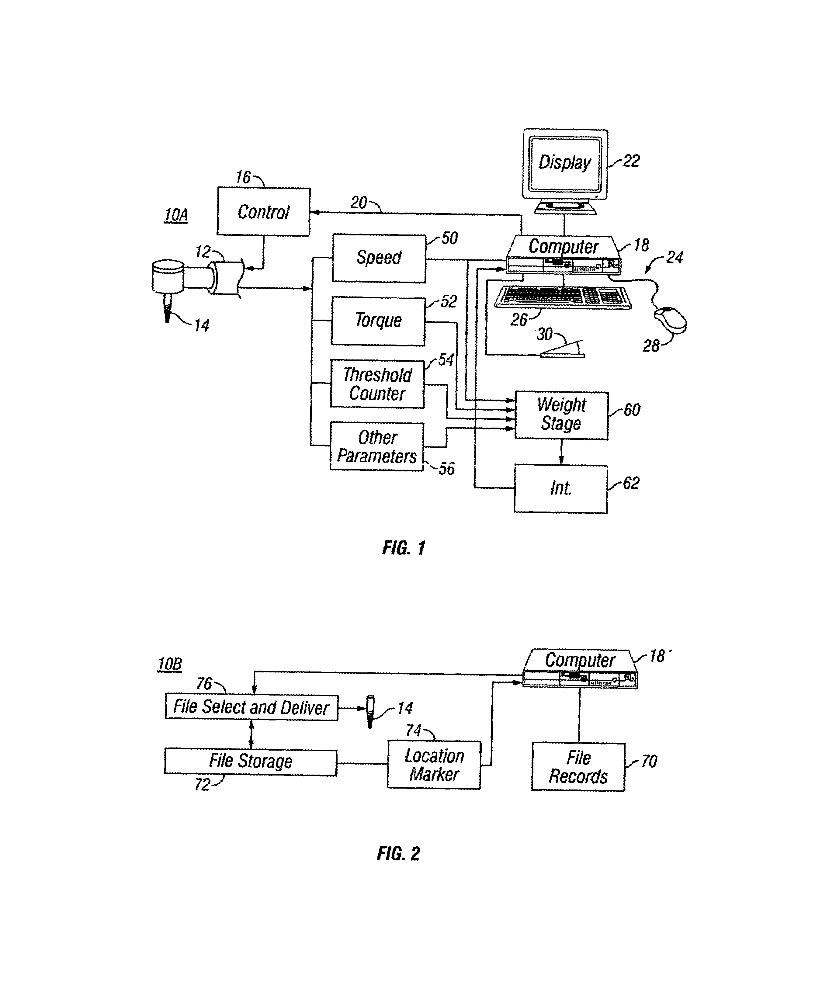
[0042]FIGS. 1 and 2 together illustrate a system 10 comprising a data collection portion 10A (FIG. 1) and a file selector portion 10B (FIG. 2).
[0043]The data collection portion 10A is shown comprising a handpiece 12 having a file 14 installed therein. The handpiece 12 is controlled in its operation by a control stage 16 which operates in response to signals from a computer 18 over a connecting line 20. Computer 18 is equipped in conventional fashion with a display device 22 and one or more input devices 24 which may be a keyboard 26, a mouse 28, a foot control 30 and / or other similar devices such as a trackball, a touchscreen, a touchpad, and the like.
[0044]The data collection portion 10A also includes a number of sensors, such as a speed sensor 50, a torque sensor 52, a threshold counter 54 and one or more sensors 56 to keep track of other parameters relating to the handpiece tool 12. Each of these sensors receives as its input corresponding outputs from the handpiece tool 12. Each...
PUM
 Abstract
Description
Claims
Application Information