
Flipper

a technology of flippers and blades, applied in the field of flippers, can solve the problems of consuming more strength and forming an increased load on the diver, and achieve the effects of increasing the side strength of the blade, good toughness and elasticity, and excessively large cross section

Inactive Publication Date: 2005-10-18
HSIEH HSING CHI
View PDF1 Cites 9 Cited by
  • Summary
  • Abstract
  • Description
  • Claims
  • Application Information

AI Technical Summary

Benefits of technology

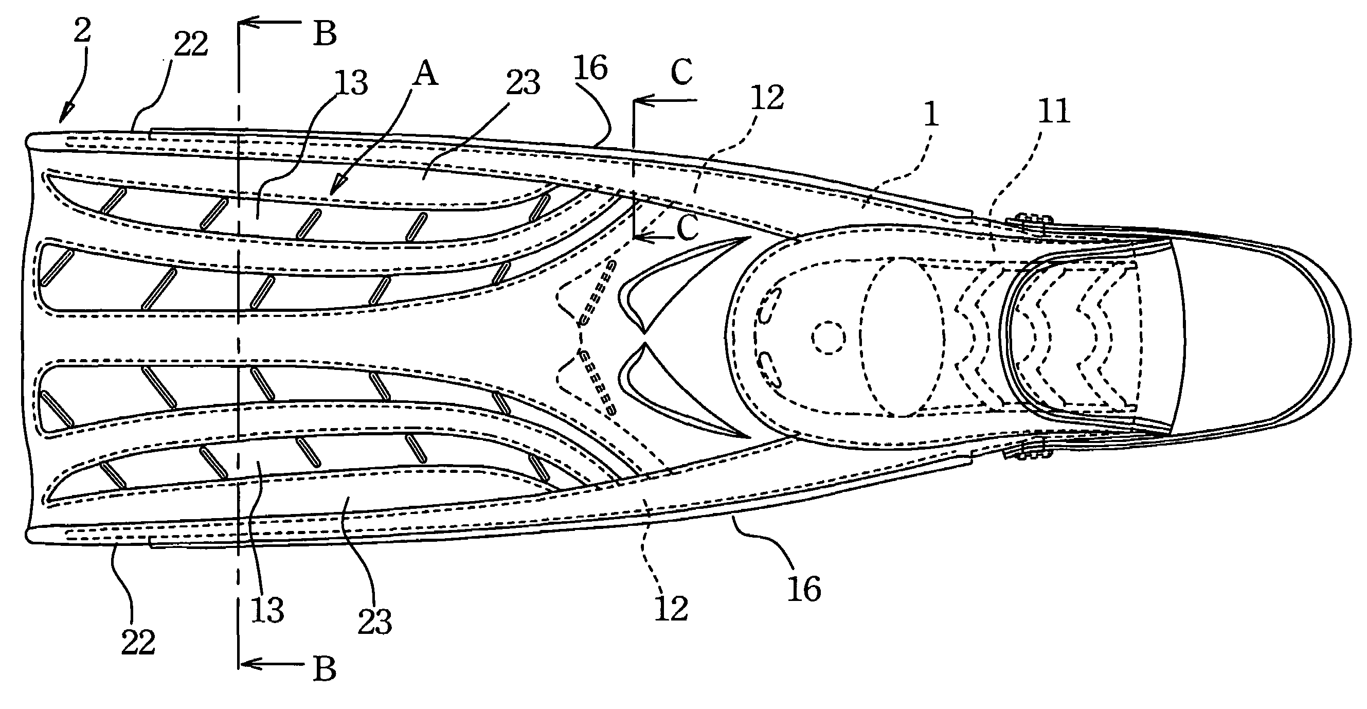
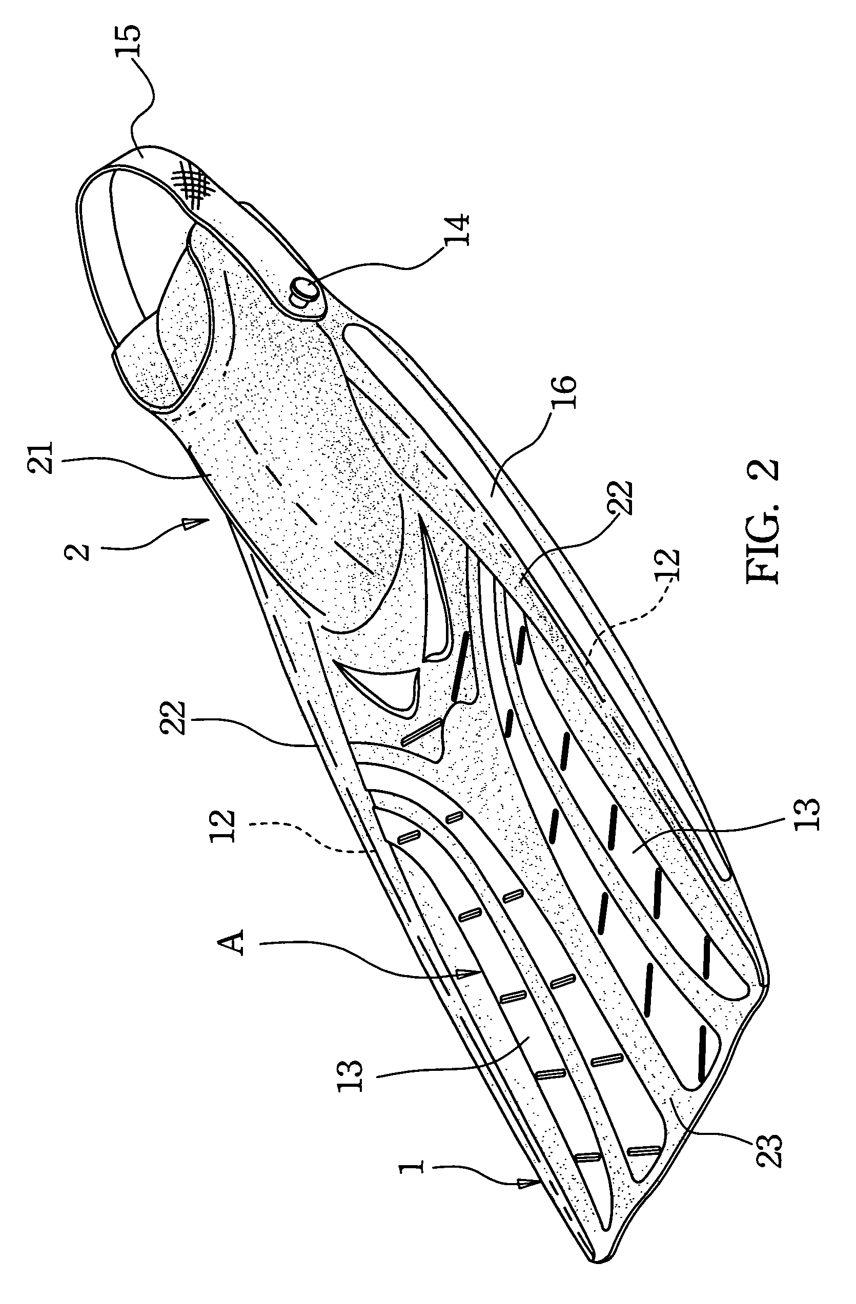
[0007]A flipper according to the present invention includes a skeleton structure having a rear base portion, two longitudinally extended side rails, and a plurality of spaced supporting strips extended in a longitudinal direction; and a web structure having a foot pocket associated with the rear base portion, two sheathings forward extended from two lateral outer sides of the foot pocket for wrapping the side rails therein, and a plurality of longitudinally extended webs provided between the two sheathings to locate between and connect two adjacent supporting strips as well as the side rails and the supporting strips. With the side rails wrapped by the sheathings, it is not necessary for the side rails to have an excessively large cross section while the sheathed side rails can still effectively increase the side strength of the blade of the flipper and give the blade good toughness and elasticity to restore from a bent and deformed state. Since the supporting strips and the webs all are longitudinally arranged on the blade of the flipper, the blade is easily deformed in a transverse direction like a bowl when the diver kicks water, and thereby increases the propelling force of the flipper.
[0008]The flipper of the present invention is also characterized in a longitudinally extended slit provided on at least one of the webs of the web structure. The slit enables a diver to kick water with reduced energy and changes the propelling force of the flipper.
[0009]The flipper of the present invention is also characterized in that the slit has a zipper provided thereat to freely adjust the length of the slit and accordingly the propelling force of the flipper.

Problems solved by technology

The thick side rails would inevitably increase the volume at two lateral sides of the blade and the overall weight of the flipper, forming an increased load to the diver to consume more strength during kicking water.

Method used


Image

  • Flipper
  • Flipper
  • Flipper

Examples


Embodiment Construction

[0019]Please refer to FIGS. 1 to 6, in which a flipper according to an embodiment of the present invention is shown. As shown, the flipper of the present invention mainly includes a skeleton structure 1, and a flexible web structure 2.

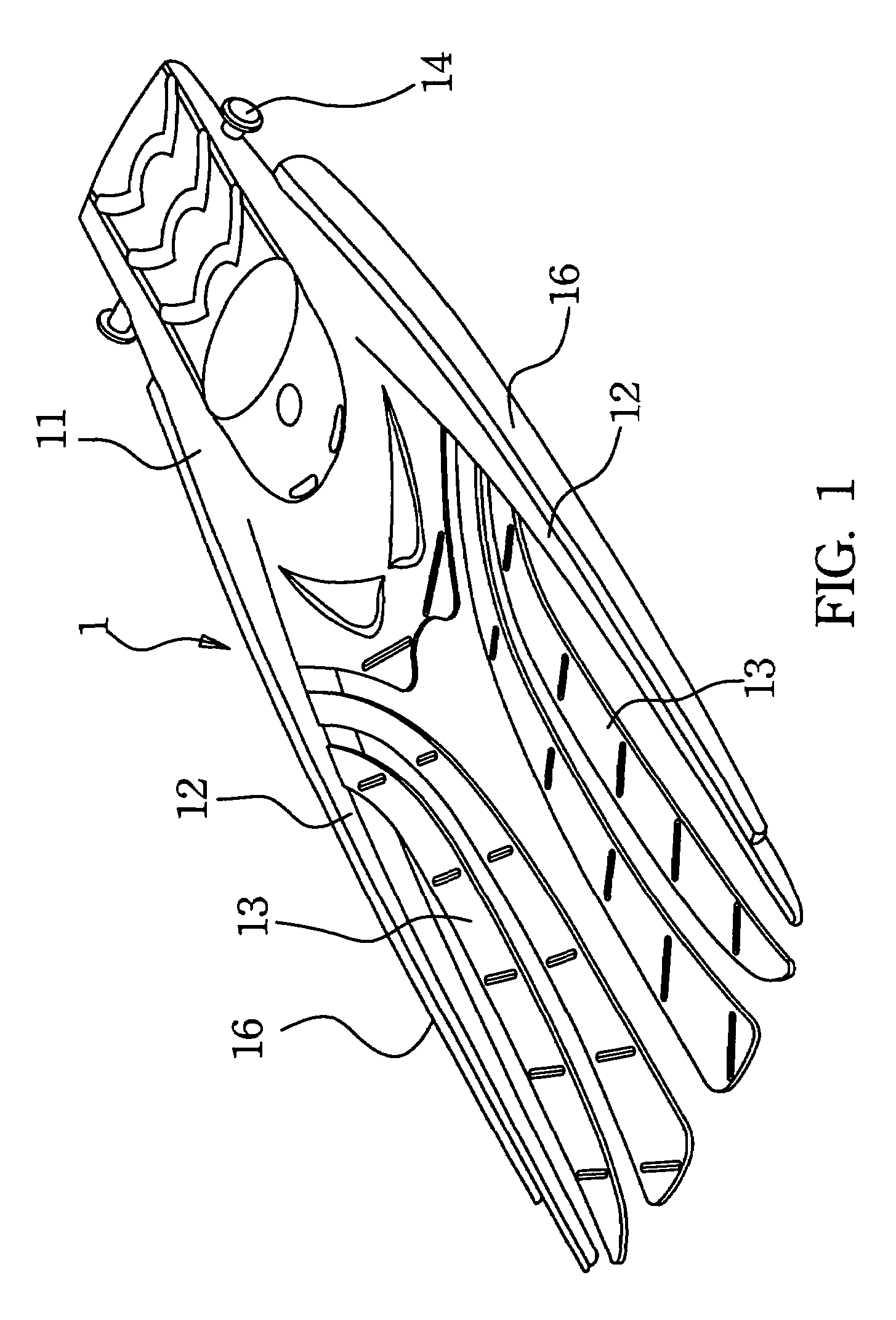
[0020]Please refer to FIG. 1 that is a perspective view of the skeleton structure 1 for the flipper of the present invention. The skeleton structure 1 is made of a tough material, such as a plastic material, and includes a rear base portion 11, a side rail 12 forward extended from each lateral side of the rear base portion 11 in a longitudinal direction of the flipper, a plurality of spaced supporting strips 13 forward extended from a rear inner side of each side rail 12 in a substantially longitudinal direction, a button 14 provided at each rear outer side of the rear base portion 11, and a heel strap 15 mounted between the two buttons 14 for fastening around a diver's heel.

[0021]FIG. 2 is a perspective view of the web structure 2 for the flipper of t...


PUM


Abstract

A flipper includes a skeleton structure having a rear base portion, two longitudinally extended side rails, and a plurality of spaced supporting strips extended in a longitudinal direction; and a web structure having a foot pocket associated with the rear base portion, two sheathings forward extended from two lateral outer sides of the foot pocket for wrapping the side rails therein, and a plurality of longitudinally extended webs provided between the two sheathings to locate between and connect two adjacent supporting strips as well as the side rails and the supporting strips. The flipper has a side rail structure with good elasticity and toughness to provide good water kicking and propelling force. A longitudinally extended slit may be provided on at least one of the webs and have a zipper provided thereat to freely adjust the length of the slit and accordingly the propelling force of the flipper.

Description

FIELD OF THE INVENTION[0001]The present invention relates to a flipper, and more particularly to a flipper having low weight and good toughness, and providing good propelling effect.BACKGROUND OF THE INVENTION[0002]A flipper has an expanded blade that enables an increased propelling force when a diver kicks water, and therefore helps the diver to move quickly under water.[0003]The blade of the flipper preferably has a proper rigidity matching the diver's kicking force, so as to produce a propelling force to move the diver forward. The blade is also provided at two outer sides with elastic and tough side rails to enhance the side strength of the blade and provide the blade with a restoring force for the blade to restore from a bent and deformed state during kicking water.[0004]The currently available flippers normally include a plurality of rigid skeleton plates obliquely arranged on the blades, and a flexible web structure associated with the skeleton plates in the process of moldin...

Claims


Application Information

Patent Timeline
IPC IPC(8): A63B31/00A63B31/08A63B31/11
CPCA63B31/11
Inventor HSIEH, HSING-CHI
Owner HSIEH HSING CHI
Learn More