
Center pillar reinforcement unit for vehicle

a technology for center pillars and vehicles, which is applied in vehicle components, superstructure subunits, transportation and packaging, etc., can solve the problems of deteriorating side strength of vehicles, affecting the energy-absorbing performance of center pillars, etc., and achieves the safety of occupants, improved energy-absorbing performance, and reduced weight of vehicles.

Active Publication Date: 2016-05-03
SUNG WOO HITECH
View PDF12 Cites 0 Cited by
  • Summary
  • Abstract
  • Description
  • Claims
  • Application Information

AI Technical Summary

Benefits of technology

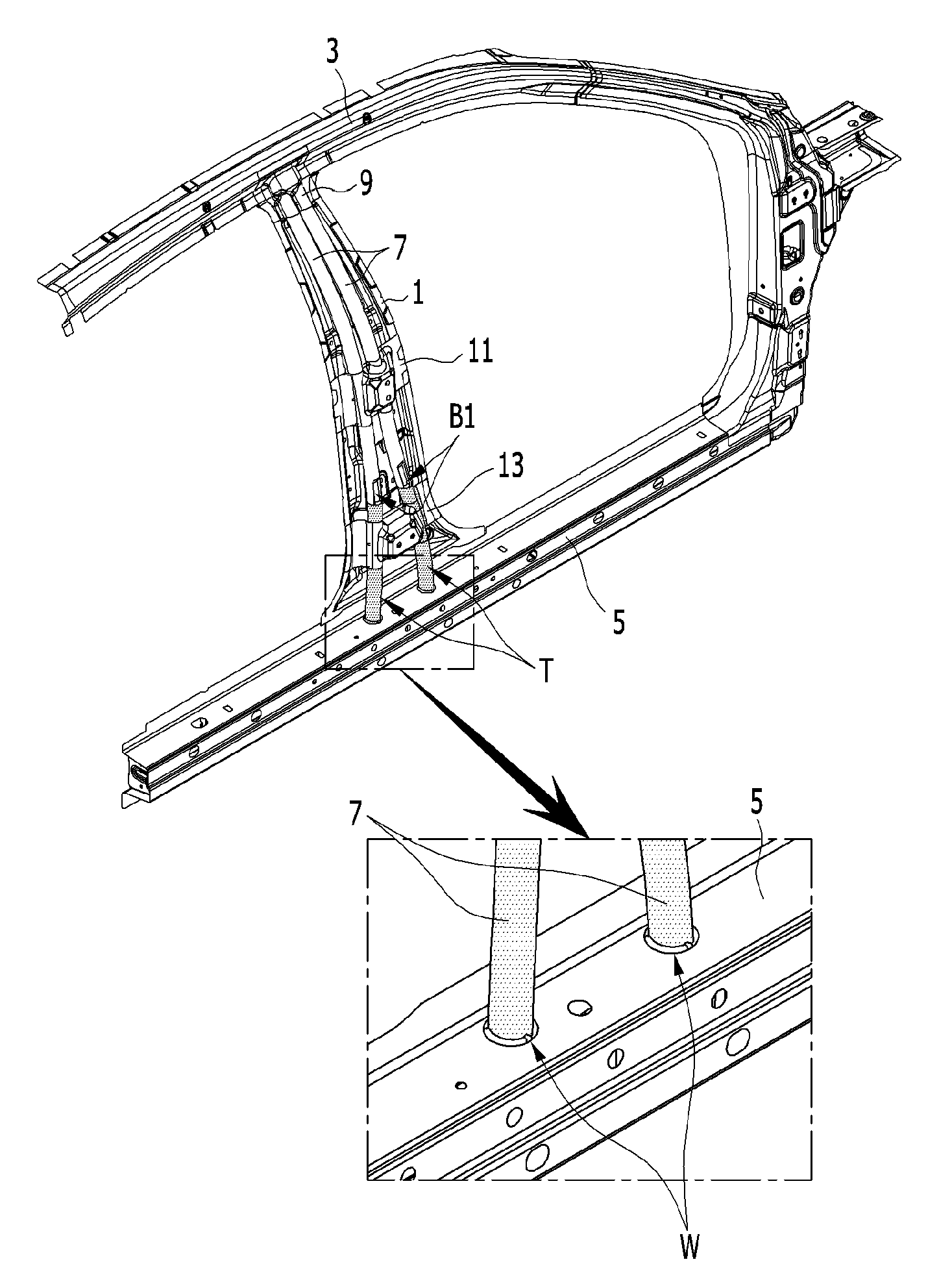
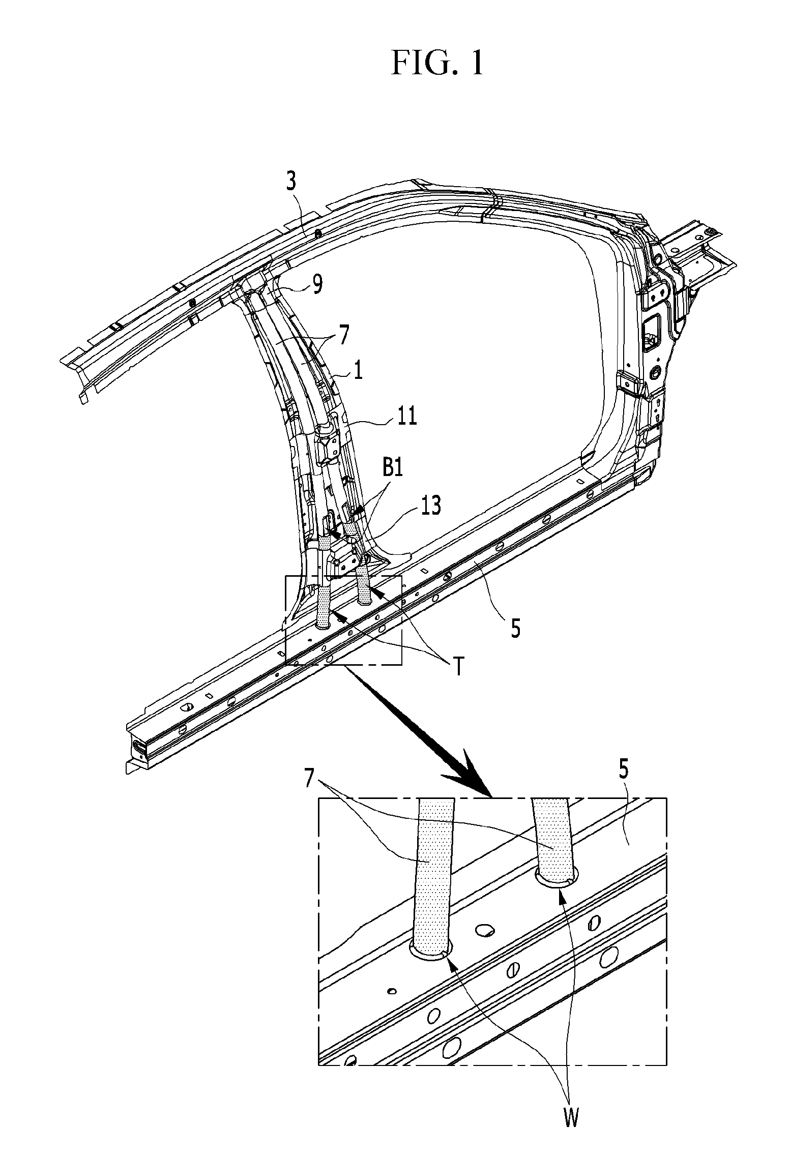
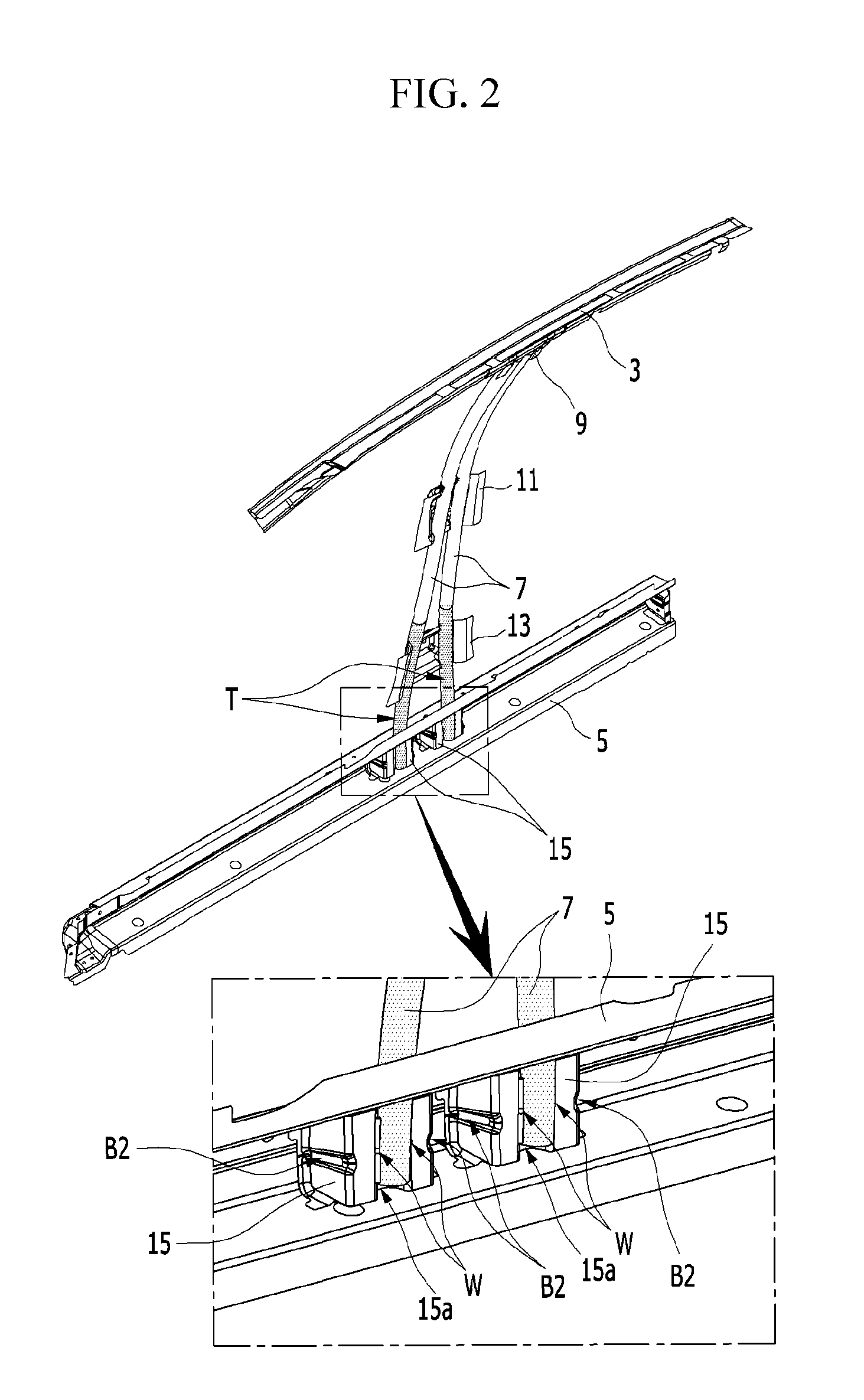
[0012]The present invention has been made in an effort to provide a center pillar reinforcement unit in which a plurality of reinforcement beams are fixed through a bracket and collision energy is induced to a side seal provided at a lower portion of a vehicle body independent of an occupant, such that energy-absorbing performance is improved and overall strength of the side vehicle body is reinforced.
[0033]Accordingly, energy-absorbing performance is improved, safety of the occupants can be ensured by reinforcing side strength of the vehicle body, a weight of the vehicle body can be reduced, and a configuration of the vehicle body can be simplified.
[0034]Further, the plurality of reinforcement beams are made of an ultra-high strength steel pipe, the predetermined section of the reinforcement beam is partially softened by a laser heat treatment, and the predetermined section of the reinforcement beam is supported to the side sill. Therefore, collision energy is absorbed therein, the collision energy is distributed to the side sill through bending of the softening processing section in a side collision, and it is possible to provide reliable energy-absorbing performance.

Problems solved by technology

At this time, since the center pillar outer panel transfers collision energy to other parts of the vehicle body, the center pillar outer panel affects energy-absorbing performance.
However, according to a prior art, the center pillar outer panel does not transfer collision energy occurring in a side collision of the vehicle in a direction independent of the occupants, and does not efficiently absorb collision energy, such that there is a problem that side strength of the vehicle is deteriorated.

Method used


Image

  • Center pillar reinforcement unit for vehicle
  • Center pillar reinforcement unit for vehicle
  • Center pillar reinforcement unit for vehicle

Examples


Embodiment Construction

[0040]Here, an exemplary embodiment of the present invention will be described in detail with reference to accompanying drawings.

[0041]The sizes and thicknesses of the configurations shown in the drawings are provided selectively for the convenience of description, such that the present invention is not limited to those shown in the drawings and the thicknesses are exaggerated to make some parts and regions clear.

[0042]The drawings and description are to be regarded as illustrative in nature and not restrictive.

[0043]FIG. 1 is an outer perspective view illustrating a center pillar reinforcement unit for a vehicle disposed to a center pillar according to an exemplary embodiment of the present invention. FIG. 2 is an inner perspective view illustrating a center pillar reinforcement unit for a vehicle disposed a center pillar according to an exemplary embodiment of the present invention. FIG. 3 is an enlarged view illustrating a reinforcement beam and welding portions applied to a cent...


PUM


Abstract

A center pillar reinforcement unit for a vehicle may include: a plurality of reinforcement beams disposed on an exterior circumference of a center pillar inner panel in a height direction; an upper bracket disposed on an upper end portion of the center pillar inner panel and a roof rail, and fixing an end portion of the plurality of reinforcement beams; a center bracket disposed on a center portion of the center pillar inner panel, and fixing a center of the plurality of reinforcement beams; a lower bracket disposed on a lower portion of the center pillar inner panel, and fixing a lower portion of the plurality of reinforcement beams; and a gusset bracket formed inside of a side sill seal so that the lower portion of the plurality of reinforcement beams is assembled.

Description

CROSS-REFERENCE TO RELATED APPLICATION[0001]This application claims priority to and the benefit of Korean Patent Application No. 10-2013-0169423 filed in the Korean Intellectual Property Office on Dec. 31, 2013, and Korean Patent Application No. 10-2014-0177808 filed in the Korean Intellectual Property Office on Dec. 10, 2014, the entire contents of which are incorporated herein by reference.BACKGROUND OF THE INVENTION[0002](a) Field of the Invention[0003]The present invention relates to a center pillar reinforcement unit for a vehicle. More particularly, the present invention relates to a center pillar reinforcement unit for a vehicle that induces collision energy caused by a side collision of the vehicle in a direction independent of an occupant and absorbs the collision energy by using a reinforcement beam disposed in a center pillar in a length direction, and accordingly, it is possible to improve energy-absorbing performance.[0004](b) Description of the Related Art[0005]General...

Claims


Application Information

Patent Timeline
Patent Type & Authority Patents(United States)
IPC IPC(8): B62D25/04
CPCB62D25/04
Inventor JUNG, YONGWOOKOO, DO-HOILEE, MUN YONG
Owner SUNG WOO HITECH
Learn More