Leg prosthesis

a leg and leg technology, applied in the field of leg prosthesis, can solve the problem that the generation of an unambiguous electrical signal for each bending position is impossible, and achieve the effect of improving the leg prosthesis

Active Publication Date: 2005-10-18
OSSEO PL GMBH
View PDF12 Cites 108 Cited by
  • Summary
  • Abstract
  • Description
  • Claims
  • Application Information

AI Technical Summary

Benefits of technology

[0008]In view of this background, the object of the present invention is to create relief for this prob

Problems solved by technology

The generation of an unambiguous electrical signal

Method used


Image

  • Leg prosthesis
  • Leg prosthesis
  • Leg prosthesis

Examples


Embodiment Construction

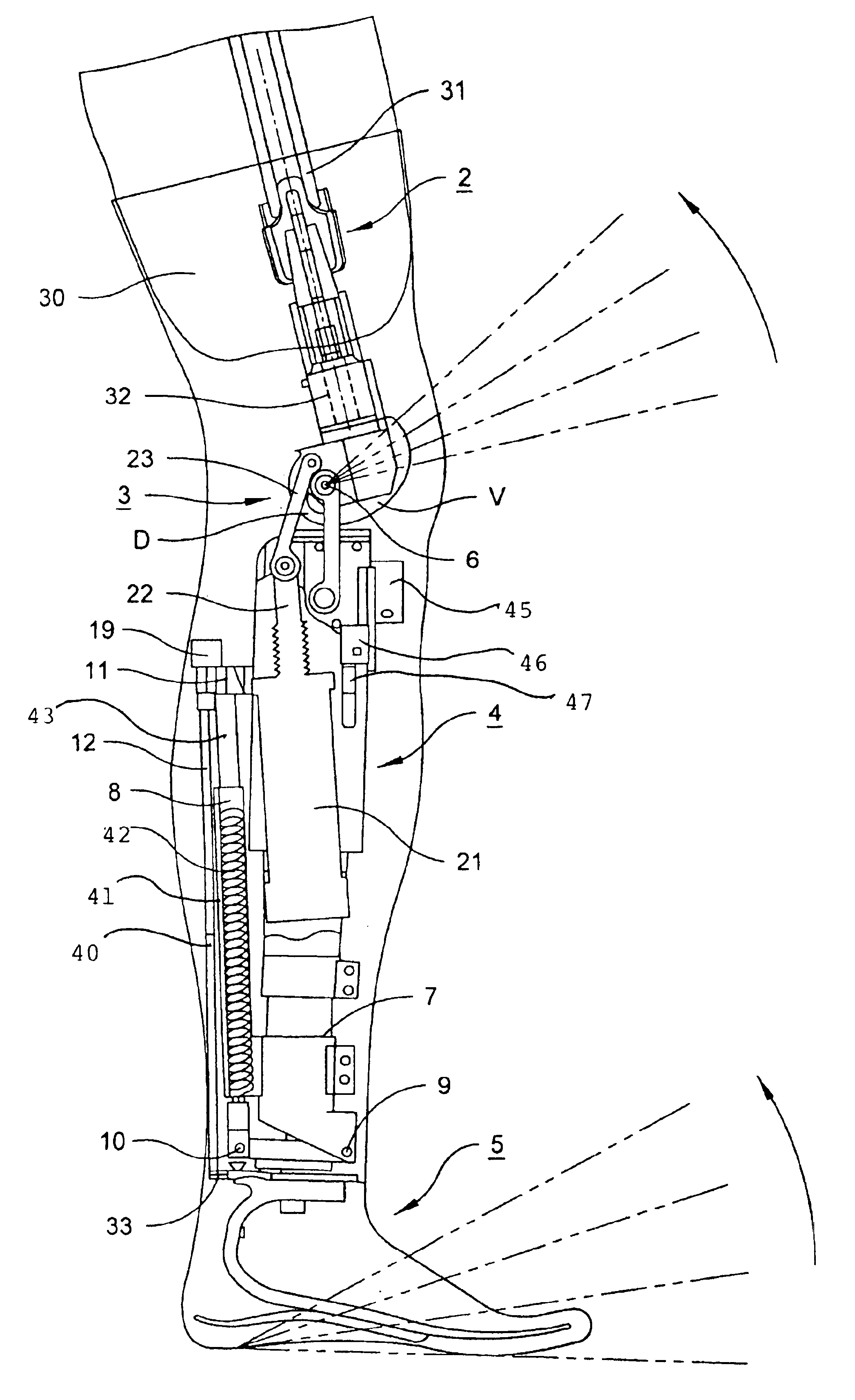
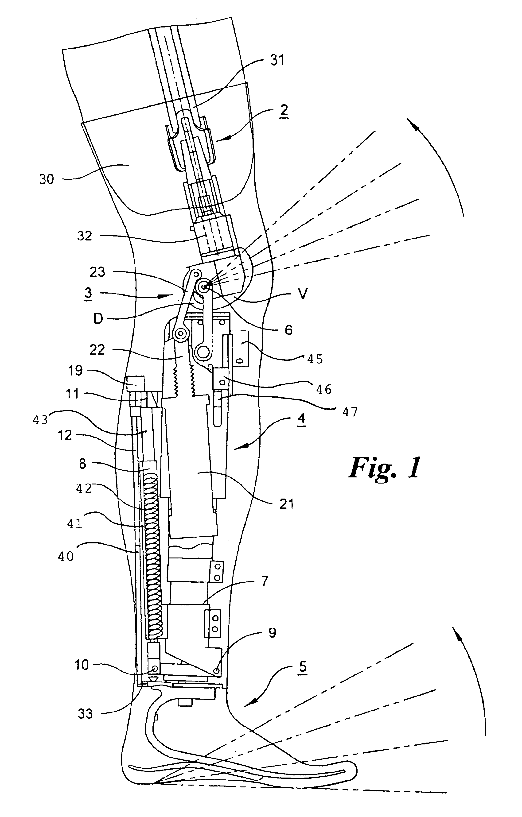
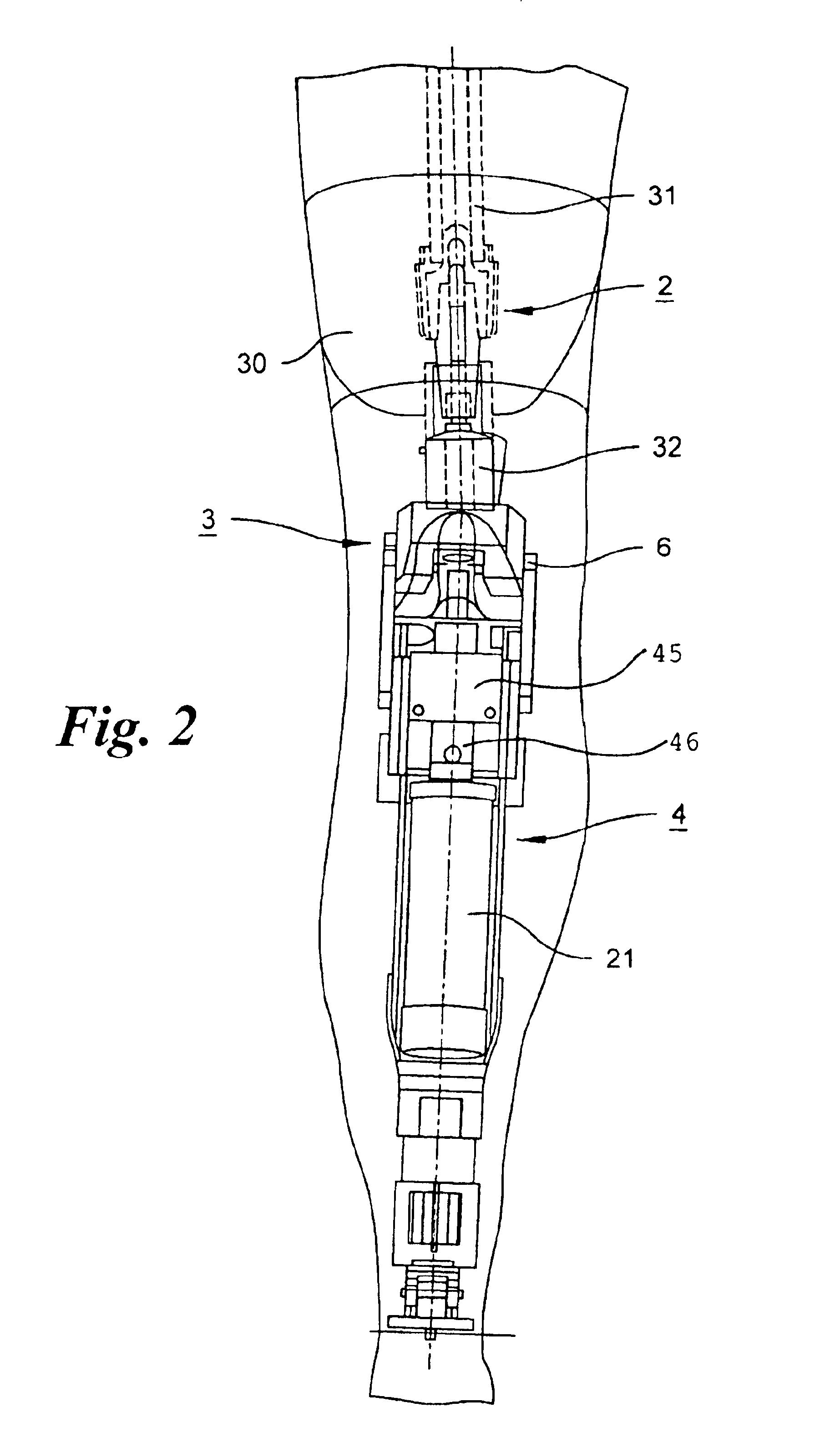
[0029]The leg prosthesis consists of an adapter 2, which is connected to the thigh stump 30 of the patient in such a manner that the adapter 2 is fixed to the femur stump 31. To the coupling element 32 of the adapter 2 a knee joint 3 is coupled, to which is connected on the distal end a prosthetic lower leg 4, which finally carries a prosthetic foot 5, in such a manner that the prosthetic foot 5 is pivotably connected to the prosthetic lower leg 4.

[0030]The knee joint 3 has a pivot axis 6, about which the upper-leg part of the knee joint 3 can pivot relative to the lower-leg part 4. The knee joint 3 has the special property that it executes a rolling-sliding movement about the pivot axis 6 during the transition from the extended position to the bending position. This leads to the fact that the distance of a point D in front of the pivot axis 6, when viewed dorsally, to the end 7 of the prosthetic lower leg 4 steadily decreases. Correspondingly, the mentioned distance for a point V i...


PUM


Abstract

A leg prosthesis adapted to a thigh stump includes an adapter (2) for a knee joint (3), a knee joint (3) mounted on this adapter, and a prosthetic lower leg (4) coupled to the knee joint (3). A prosthetic foot (5) is attached to this prosthetic lower leg and can pivot into a toes-raised foot position. The knee joint (3) upon transition from the extended position to the bent position performs a combined rolling-sliding movement about a pivot axis (6). A force-transmitting element (8) moves the prosthetic foot (5) substantially from the toes-down foot position to the toes-raised foot position during bending of the knee joint (3). Each bending position of the knee joint is transformed by a converter into an unambiguous electrical signal, which is supplied to a programmable control device, which generates a signal used to control an electrically adjustable actuator, which increases or decreases the resistance of the knee joint against or for further bending according to the signal.

Description

BACKGROUND OF THE INVENTION[0001]The present invention is directed to a leg prosthesis for adapting to a thigh stump, as known from German published patent application DE-A-199 53 972. It comprises an adapter for a knee joint, which adapter is anchored in the femur stump of the patient with a post. At the distal end the adapter emerges from the thigh stump and there it can be coupled to an artificial knee joint, as known, for example, from European Patent EP-B-0 358 056.[0002]A prosthetic lower leg, which in turn carries an attached prosthetic foot at its distal end, is coupled to the knee joint. This prosthetic foot can pivot from a pointed (toes-down) foot position to a cocked (toes-raised) foot position.[0003]The knee joint according to the proposal of European Patent EP-B-0 358 056 is formed such that for the transition from the extended position to the bent position, it carries out a combined rolling and sliding motion about a pivot axis. In contrast to a pure hinge joint, the ...

Claims


Application Information

Patent Timeline
IPC IPC(8): A61F2/50A61F2/68A61F2/60A61F2/64
CPCA61F2/60A61F2/68A61F2/70
Inventor GRUNDEI, HANS
Owner OSSEO PL GMBH
Why Eureka
Try Eureka