Coaxial inductor and dipole EH antenna

a dipole eh, coaxial inductor technology, applied in the field of radio frequency communication, can solve the problems of requiring a complicated physical structure, typical wire antennas require a substantial amount of space, and cross-field antennas have the disadvantage of requiring complicated physical structures

Inactive Publication Date: 2005-10-18
ALPHA COGNETICS
View PDF25 Cites 108 Cited by
  • Summary
  • Abstract
  • Description
  • Claims
  • Application Information

AI Technical Summary

Benefits of technology

[0009]In another aspect, the invention is an antenna for use with a signal cable having a signal lead and a common lead. The antenna includes an insulating elongated support member. A first cylindrical conductor is disposed about a first portion of the support member. The first cylindrical conductor has a proximal end and an opposite distal end. A second cylindrical conductor is disposed about a second portion of the support member and is spaced apart from the first cylindrical member. The second cylindrical conductor has a proximal end and an opposite distal end. The proximal end is in electrical communication with the common lead. A conductive coil is coiled about the elongated supp...

Problems solved by technology

Thus, the typical wire antenna requires a substantial amount of space as a function of the wavelength being transmitted and received.
The Crosse...

Method used


Image

  • Coaxial inductor and dipole EH antenna
  • Coaxial inductor and dipole EH antenna
  • Coaxial inductor and dipole EH antenna

Examples


Embodiment Construction

[0018]A preferred embodiment of the invention is now described in detail. Referring to the drawings, like numbers indicate like parts throughout the views. As used in the description herein and throughout the claims, the following terms take the meanings explicitly associated herein, unless the context clearly dictates otherwise: the meaning of “a,”“an,” and “the” includes plural reference, the meaning of “in” includes “in” and “on.”

[0019]A general discussion of Poynting vector theory may be found in the disclosure of U.S. Pat. Nos. 5,155,495 and 6,025,813, which are incorporated herein by reference.

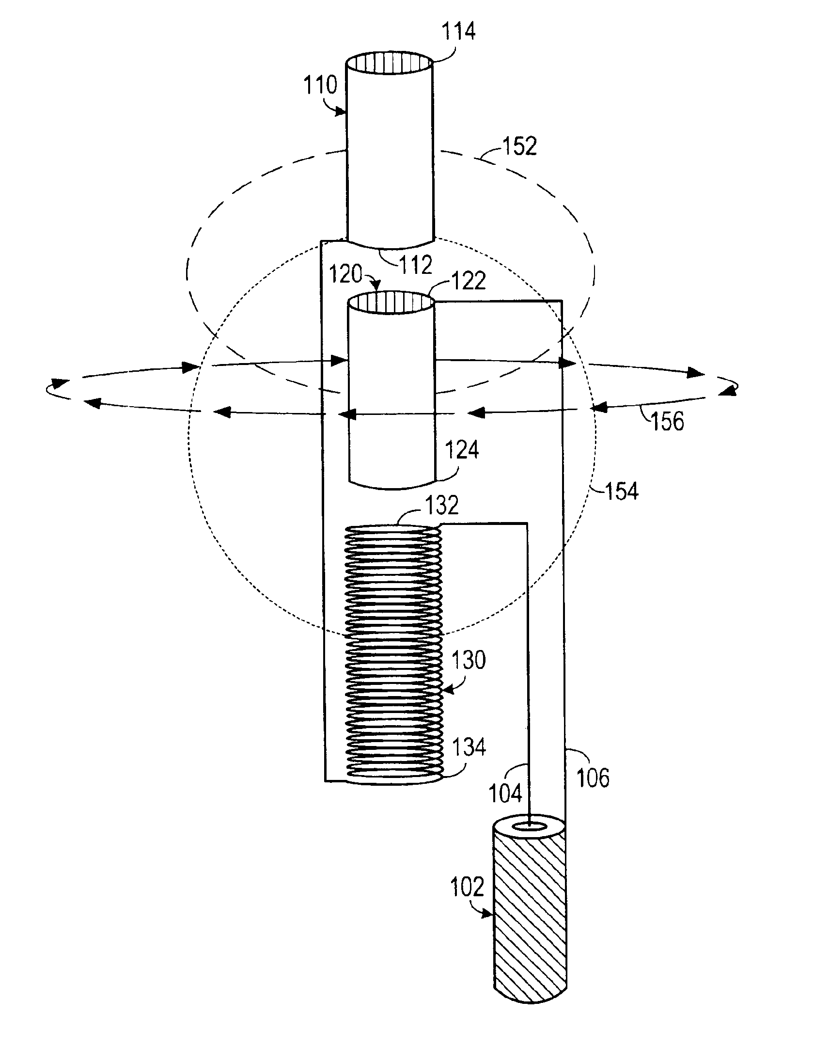
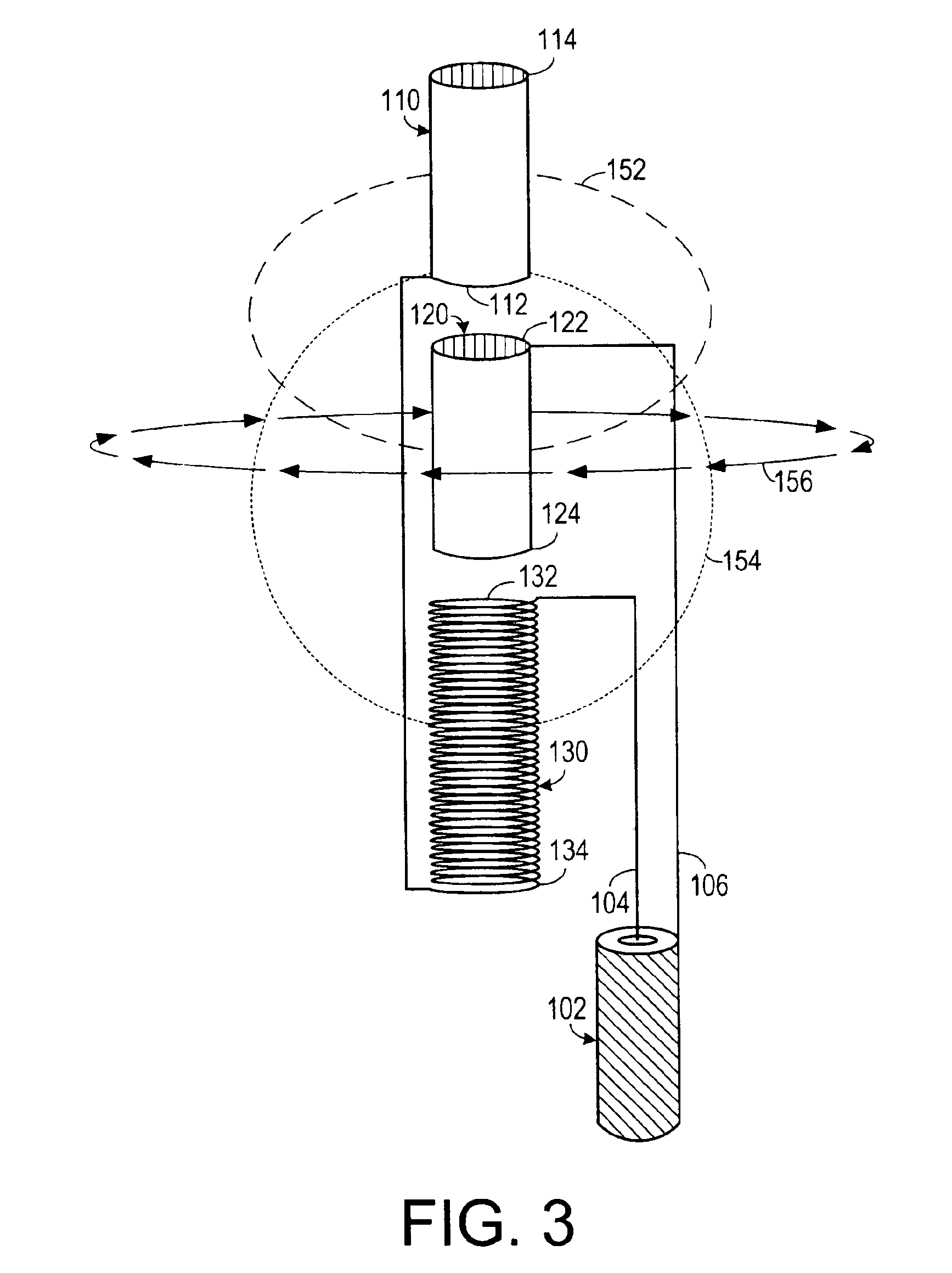
[0020]The concept of the invention is based on the Poynting Theorem, where S=E×H. If an E field and an H field are developed and they have the proper relationship in amplitude, time (phase) and physical relationship, radiation will be developed.

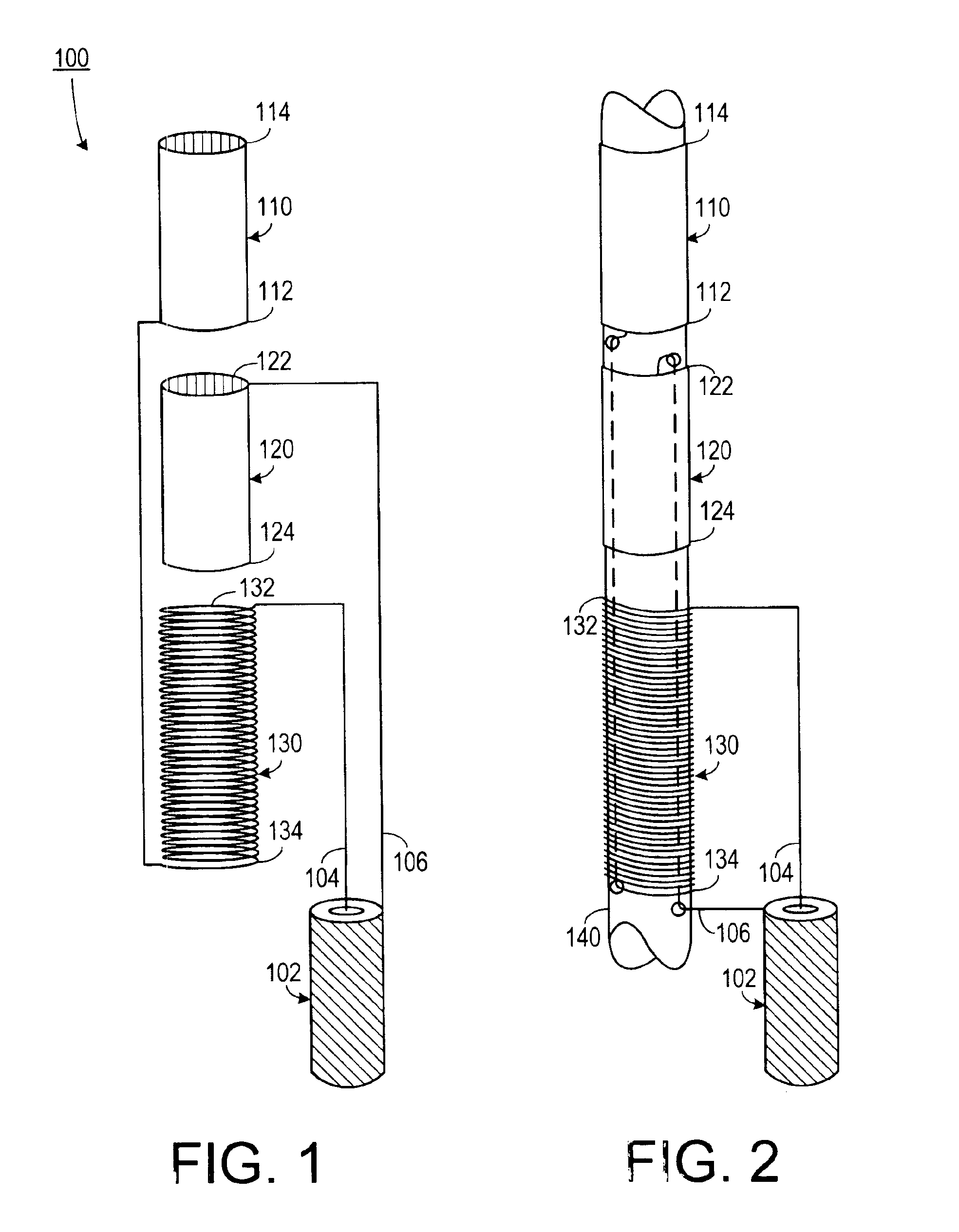
[0021]As shown in FIG. 1, one embodiment of the invention includes an antenna 100 for use with a signal cable 102 having a signal lead 104 and a ...


PUM


Abstract

An antenna for generating radiation includes a primary E-field generating circuit and a secondary E-field generating circuit. The primary E-field generating circuit generates a primary E-field in response to a source RF signal being applied to the antenna. The secondary E-field generating circuit generates a secondary E-Field, disposed apart from the primary E-field, in response to the source RF signal and develops an H-field that is in time phase with the primary E-field. This causes the antenna to develop a radiation resistance as an indication of radiation.

Description

BACKGROUND OF THE INVENTION[0001]1. Field of the Invention[0002]The present invention relates to radio frequency communications and, more specifically, to an antenna system employed in radio frequency communications.[0003]2. Description of the Prior Art[0004]Radio signals usually start with electrical signals that have been modulated onto a radio frequency carrier wave. The resulting radio signal is transmitted using an antenna. The antenna is a system that generates an electrical field (E field) and a magnetic field (H field) that vary in correspondence with the radio signal, thereby forming radio frequency radiation. At a distance from the antenna, as a result of transmission effects of the medium through which the radio frequency radiation is being transmitted, the E field and the H field fall into phase with each other, thereby generating a Poynting vector, which is given by S=E×H, where S is the Poynting vector, E is the E field vector and H is the H field vector.[0005]Conventi...

Claims


Application Information

Patent Timeline
IPC IPC(8): H01Q9/04H01Q9/16
CPCH01Q9/16
Inventor HART, ROBERT T.
Owner ALPHA COGNETICS
Why Eureka
Try Eureka