This helps you quickly interpret patents by identifying the three key elements:
Problems solved by technology
Method used
Benefits of technology
[0010]Accordingly, embodiments of the present invention provide a structure that allows for the beam forming network associated with one or more antenna element sub-array to be reconfigured independently of the beam forming network associated with another one or more antenna element sub-array. Preferred embodiments of the present invention utilize beam forming personality modules associated with one or more sub-arrays to facilitate independent configuration/reconfiguration of beam forming networks of the various sub-arrays. Such personality modules are preferably passive or active beam forming networks provided in removable modules for interfacing with antenna elements of a particular sub-array.
[0011]In implementing antenna arrays of the present invention, wherein sub-arrays utilized for different communication services and/or communication providers reside in the same antenna array, it is desirable to adapt the antenna array to mitigate/prevent interference between the sub-arrays, such as by providing sufficient isolation between the antenna elements of the various sub-arrays. Accordingly, preferred embodiments of the present inve
Problems solved by technology
Moreover, the beam forming pattern that is used for each ind
Method used
Image
Click on the blue label to locate the original text in one second.
Reading with bidirectional positioning of images and text.
Examples
Embodiment Construction
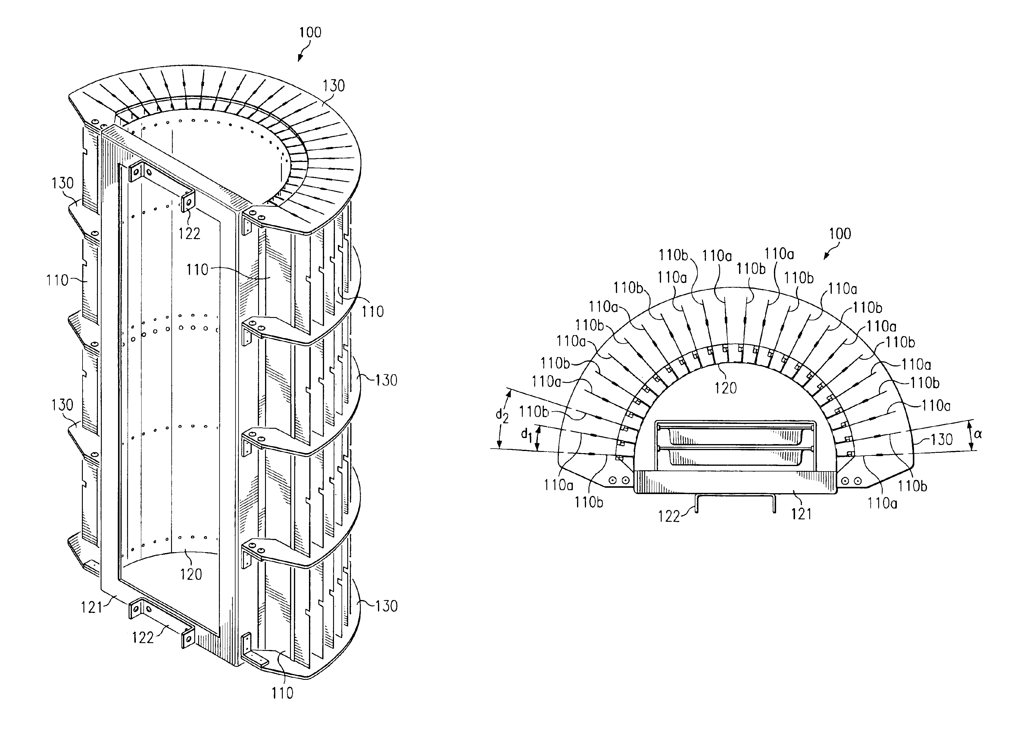
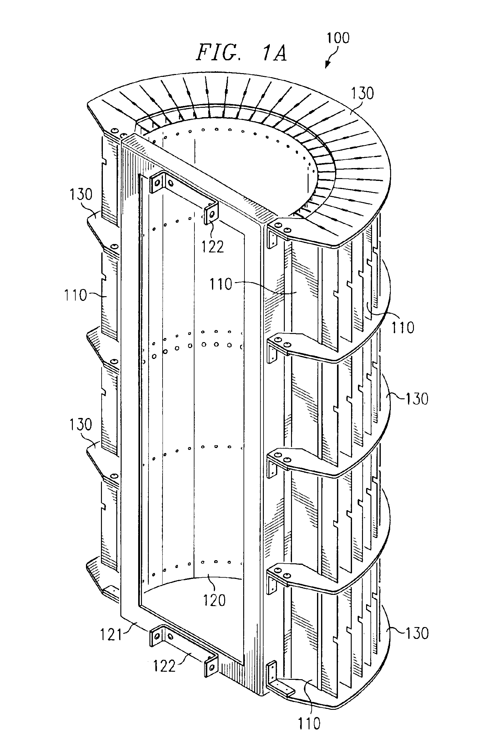
[0027]Directing attention to FIGS. 1A and 1B, a preferred embodiment antenna array configuration is shown as antenna array 100. Antenna array 100 of the illustrated embodiment includes a plurality of antenna element assemblies 110, each including one or more antenna elements. According to a preferred embodiment, antenna element assemblies 110 each comprise a plurality of individual antenna elements, such as dipole, log-periodic, Yagi, slotted-waveguide, patch, helical, horn, and / or like antenna elements, forming an antenna element column.
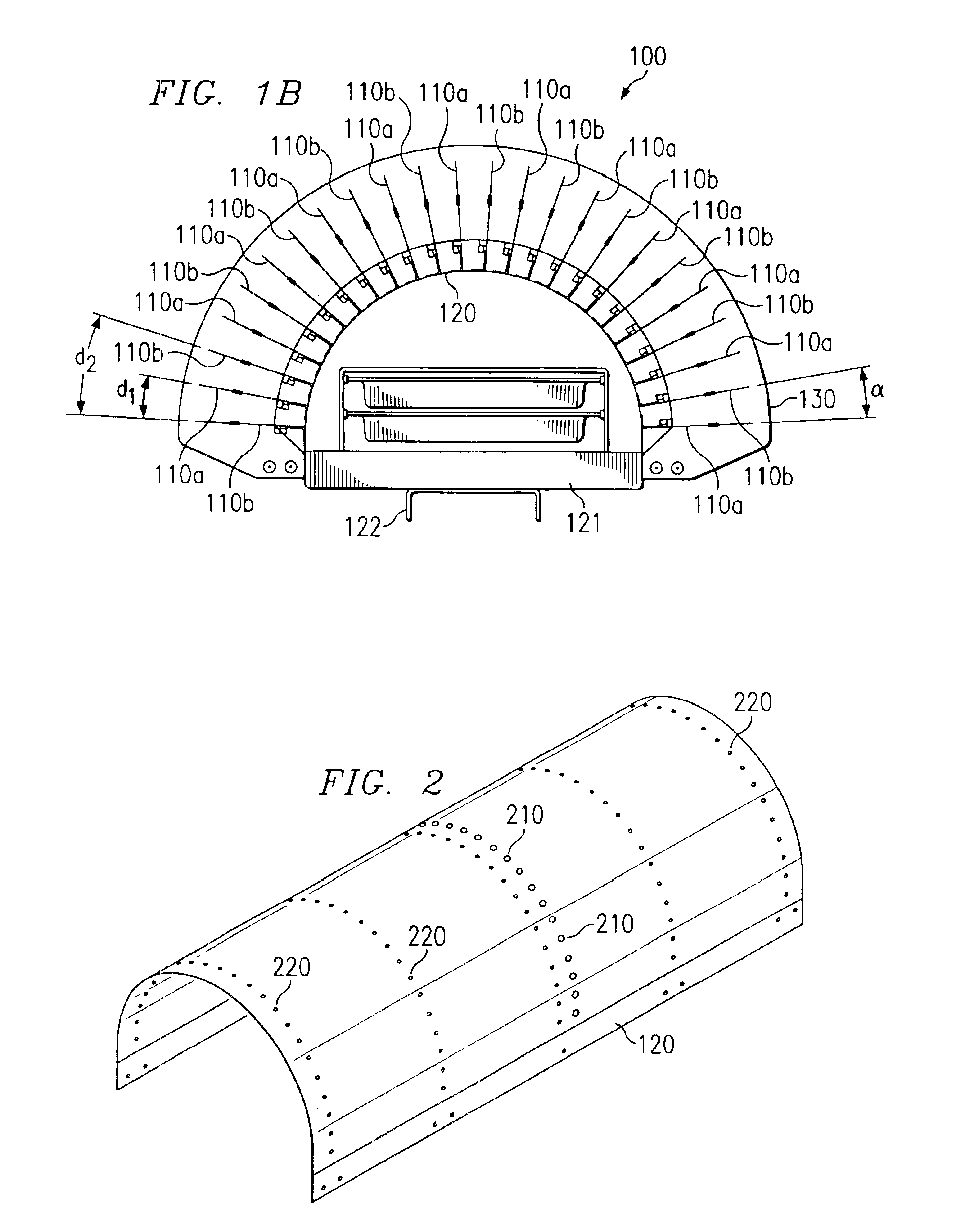
[0028]Antenna element assemblies 110 are preferably disposed in a predetermined orientation to define an antenna array. Accordingly, antenna elements of the illustrated embodiment are coupled to shell 120, providing a cylindrical configuration in the illustrated embodiment. Shell 120 preferably provides mechanical support for antenna element assemblies 110. Accordingly, shell 120 includes frame 121 and mounting bracket 122 to provide rigidity and / or...
PUM
Abstract
Disclosed is an integrated antenna array comprising a plurality of interleaved sub-arrays separately controllable and responding to either the same or separate frequency bands. Both arrays operate with substantially the same phase center and substantially within the same effective aperture. The first sub-array of array comprises of spaced linear radiating elements such as dipoles, log-periodic, Yagi, slotted-waveguide, patch, or array consisting of the same or different elements as used in the first sub-array, either on the same or an entirely different frequency band. Independent beam shaping systems are shown for independent operation of the two arrays.
Description
REFERENCE TO RELATED APPLICATIONS[0001]The present application is related to, and hereby claims priority to, co-pending and commonly assigned U.S. provisional patent applications Ser. No. 60 / 322,573 entitled “Co-Located Antenna Array for Passive Beam Forming,” filed Sep. 12, 2001, Ser. No. 60 / 322,542 entitled “Automated Process for Generating Arbitrary Passive Beam Forming Networks,” filed Sep. 12, 2001, Ser. No. 60 / 322,494 entitled “Inexpensive Fabrication Technique for Making Antenna Element Cards,” filed Sep. 12, 2001, and Ser. No. 60 / 342,571 entitled “Co-Located Antenna Array for Passive Beam Forming,” filed Dec. 20, 2001, the disclosures of which are incorporated herein by reference in their entirety. The present application is also related to commonly assigned U.S. patent applications Ser. No. 10 / 242,311 entitled “Generating Arbitrary Passive Beam Forming Networks,” concurrently filed herewith, Ser. No. 09 / 878,599 entitled “Passive Shapable Sectorization for Cellular Networks,...
Claims
Application Information
Patent Timeline
Application Date:The date an application was filed.
Publication Date:The date a patent or application was officially published.
First Publication Date:The earliest publication date of a patent with the same application number.
Issue Date:Publication date of the patent grant document.
PCT Entry Date:The Entry date of PCT National Phase.
Estimated Expiry Date:The statutory expiry date of a patent right according to the Patent Law, and it is the longest term of protection that the patent right can achieve without the termination of the patent right due to other reasons(Term extension factor has been taken into account ).
Invalid Date:Actual expiry date is based on effective date or publication date of legal transaction data of invalid patent.