Differential visualization of countoured surfaces

Inactive Publication Date: 2005-10-18
SIEMENS AG
View PDF1 Cites 7 Cited by
  • Summary
  • Abstract
  • Description
  • Claims
  • Application Information

AI Technical Summary

Benefits of technology

[0017]The computational complexity can be reduced by determining from workpiece data a plurality of discrete support points in three-dimensional space, and by determining for each surface a grid surface based on the discrete support points. The spatial difference between the grid surfaces of the first and second surface can then be obtained by forming a difference between corresponding support points located on the first and second grid surfaces.
[0018]The grid surfaces can be conven

Problems solved by technology

However, this approach is very time consuming and expensive, and wastes material.
Moreover, the cause for deviations between the actually manufactured workpiece and the desired workpiece it is f

Method used


Image

  • Differential visualization of countoured surfaces
  • Differential visualization of countoured surfaces
  • Differential visualization of countoured surfaces

Examples


Embodiment Construction

[0028]Throughout all the Figures, identical or corresponding elements are generally indicated by same reference numerals.

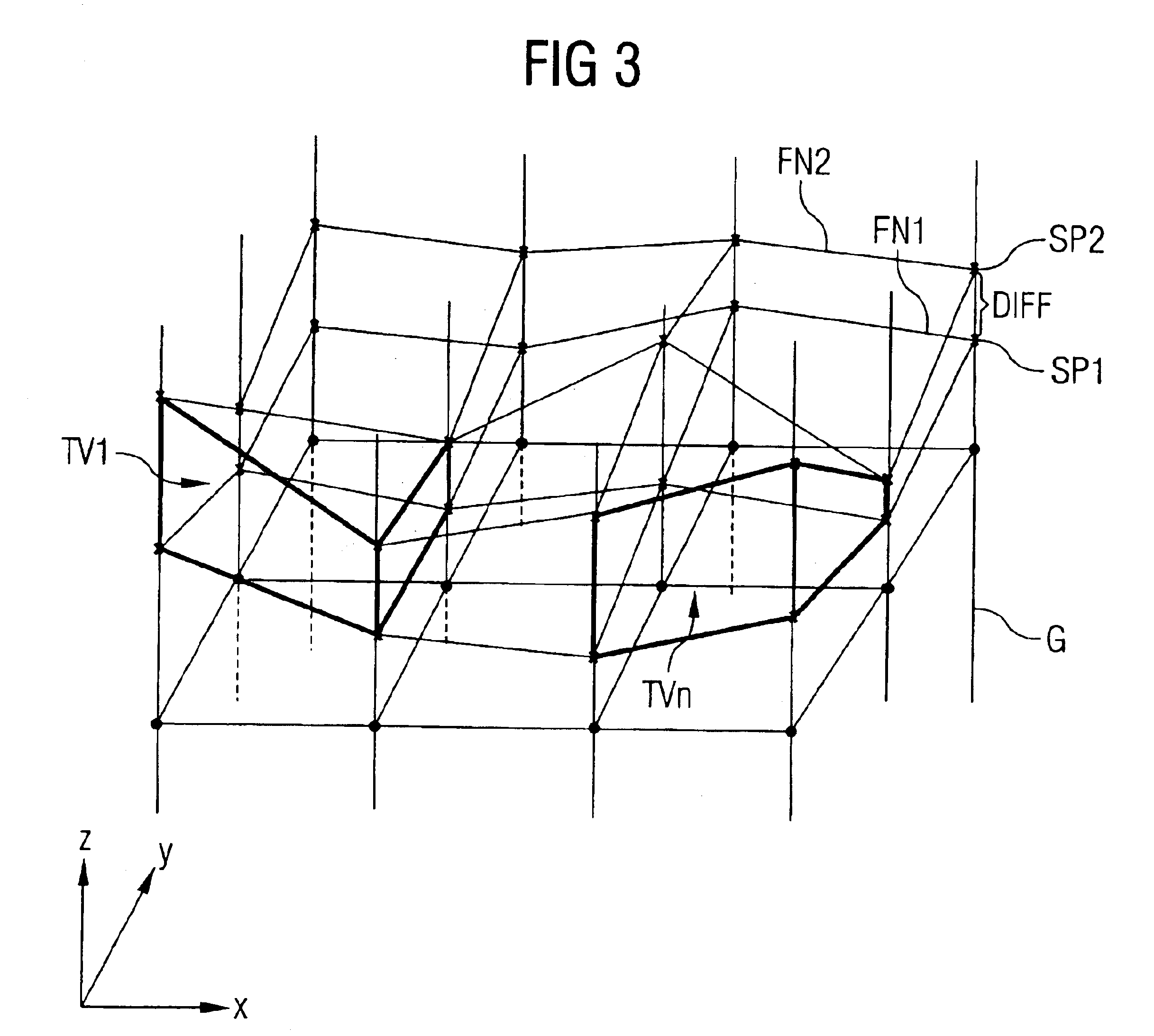
[0029]The invention is directed to a method for determining a grid surface for a workpiece processed with a virtual milling process with three axes, and to a differential visualization on the basis of two such grid surfaces.

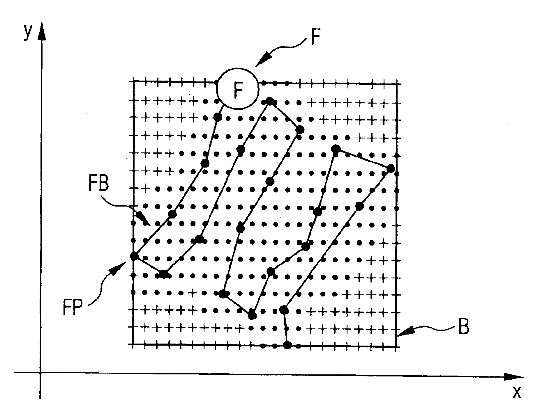
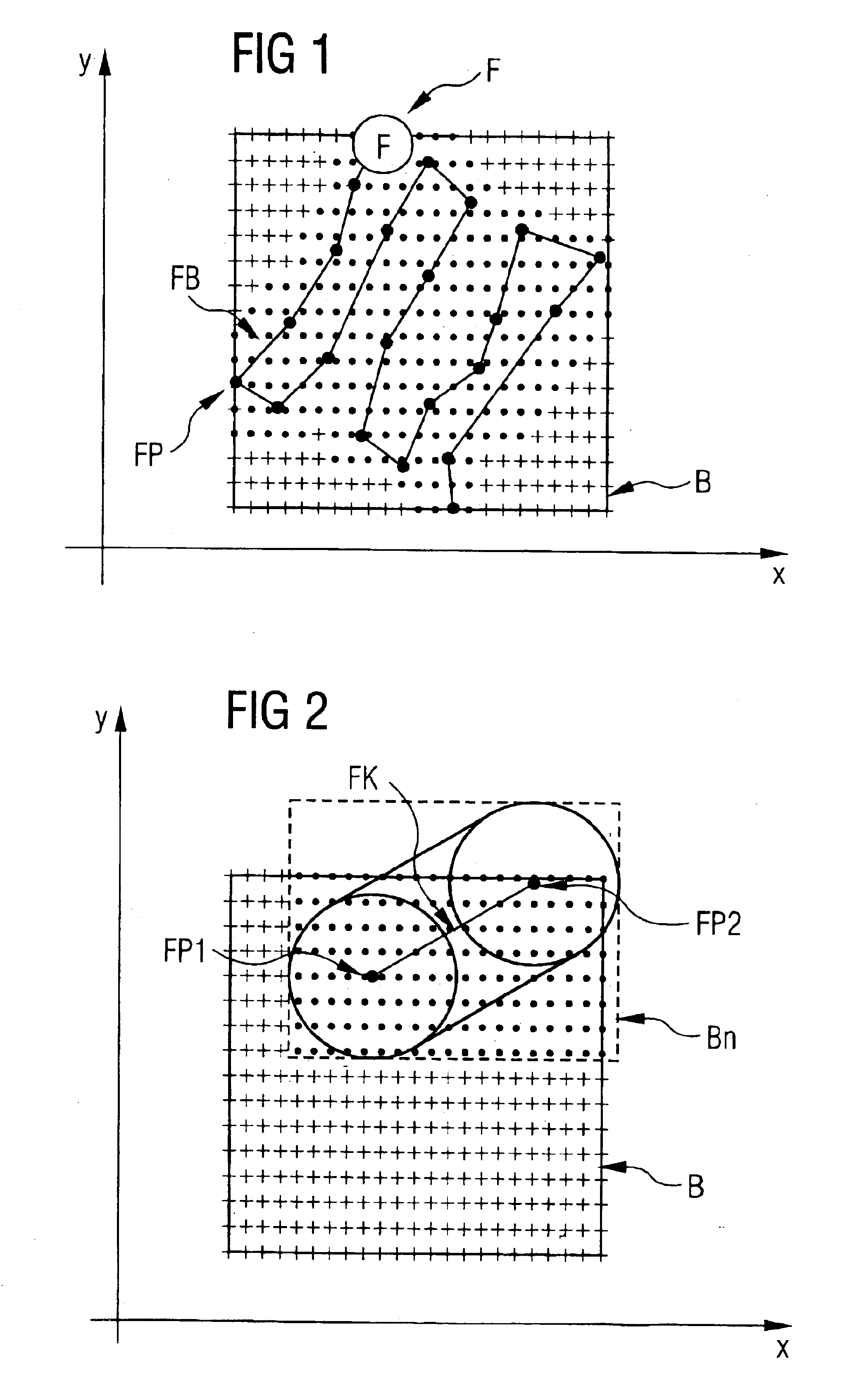
[0030]The grid surface can be determined, for example, based on uniformly spaced straight lines that extend in the x-and y-direction and are parallel to the vertical z-axis. Preferably, the allowed straight lines must have point-shaped orthogonal projections in the xy-plane that are located inside a rectangle having mutually parallel axes (the definition of the rectangle will be discussed in more detail below). The family of straight lines models a blank workpiece which is represented by discrete data points in the x-and y-direction and extends to infinity along the positive and negative z-direction.

[0031]FIG. 1 shows schematically in a two-dim...


PUM


Abstract

A method and a system for visualizing differences of three-dimensional contour surfaces, in particular of three-dimensional contour surfaces produced by virtually machining a workpiece, are described. The method determines a first and second surface and spatial and/or volume differences between the contours of these surfaces. One of the surfaces together with the determined spatial and/or volume differences between the contours of the surfaces can be graphically rendered, wherein the differences are rendered as an additional attribute of the one surface, for example, in a different color.

Description

CROSS-REFERENCES TO RELATED APPLICATIONS[0001]This application claims the priority of German Patent Application Serial No. 101 45 515.1, filed Sep. 14, 2001, pursuant to 35 U.S.C. 119(a)-(d), the subject matter of which is incorporated herein by reference.BACKGROUND OF THE INVENTION[0002]The present invention relates to a method for the visualization of differences between three-dimensional contoured surfaces, as well as to an apparatus for carrying out the method, in particular a simulation computer.[0003]In CNC-controlled processing machines, a workpiece is typically either encoded directly or the workpiece is first modeled using a CAD system and thereafter converted into an equivalent CNC parts program. The resulting CNC parts programs and / or the CAD model then correspond to perfect processing commands for the processing machine. The CNC programs is then loaded into a CNC controller and the processing machine is controlled according to the CNC program.[0004]If the workpiece manuf...

Claims


Application Information

Patent Timeline
IPC IPC(8): G06T15/00
CPCG06T15/00
Inventor SINN, CHRISTOF
Owner SIEMENS AG
Why Eureka
Try Eureka