Shock mounting system for CCD camera

a technology of shock mounting system and ccd camera, which is applied in the field of shock mounting electronic devices, can solve the problems of reducing image resolution or eliminating it entirely, affecting the image quality of the image, and being more expensive than a single ccd camera

Inactive Publication Date: 2005-10-18
LINVATEC
View PDF5 Cites 22 Cited by
  • Summary
  • Abstract
  • Description
  • Claims
  • Application Information

AI Technical Summary

Benefits of technology

[0010]In particular, each CCD and associated glass segment is arrayed adjacent a main prism within a common plane perpendicular to a window in the housing. A pair of symmetrical support plates is used to join the CCD, glass blocks and prism together, one on each side of the camera assembly. Each support plate comprises a first planar leg for being adhered to the first CCD and associated components, a second planar leg, coplanar with the first planar leg, for being adhered to the second CCD and associated components, and a third planar leg, coplanar with the first and second legs, for being adhered to the third CCD and associated components. A support projection extends outwardly from the plane of the first, second and third legs in longitudinal alignment with the CCD viewing direction. An elastomeric boot is interposed between the housing and the support plates. The boot has a front panel having an aperture to permit image access to the main prism and spaced first and second side panels parallel to the common plane for receiving the first and second supp

Problems solved by technology

The negative side of the 3-CCD camera is that it is larger, heavier, more expensive than a single CCD camera, and the adhesive assembled glass prism and CCD assembly is easily damaged by rough handling.
Further, the recombination of the three primary color images

Method used


Image

  • Shock mounting system for CCD camera
  • Shock mounting system for CCD camera
  • Shock mounting system for CCD camera

Examples


Embodiment Construction

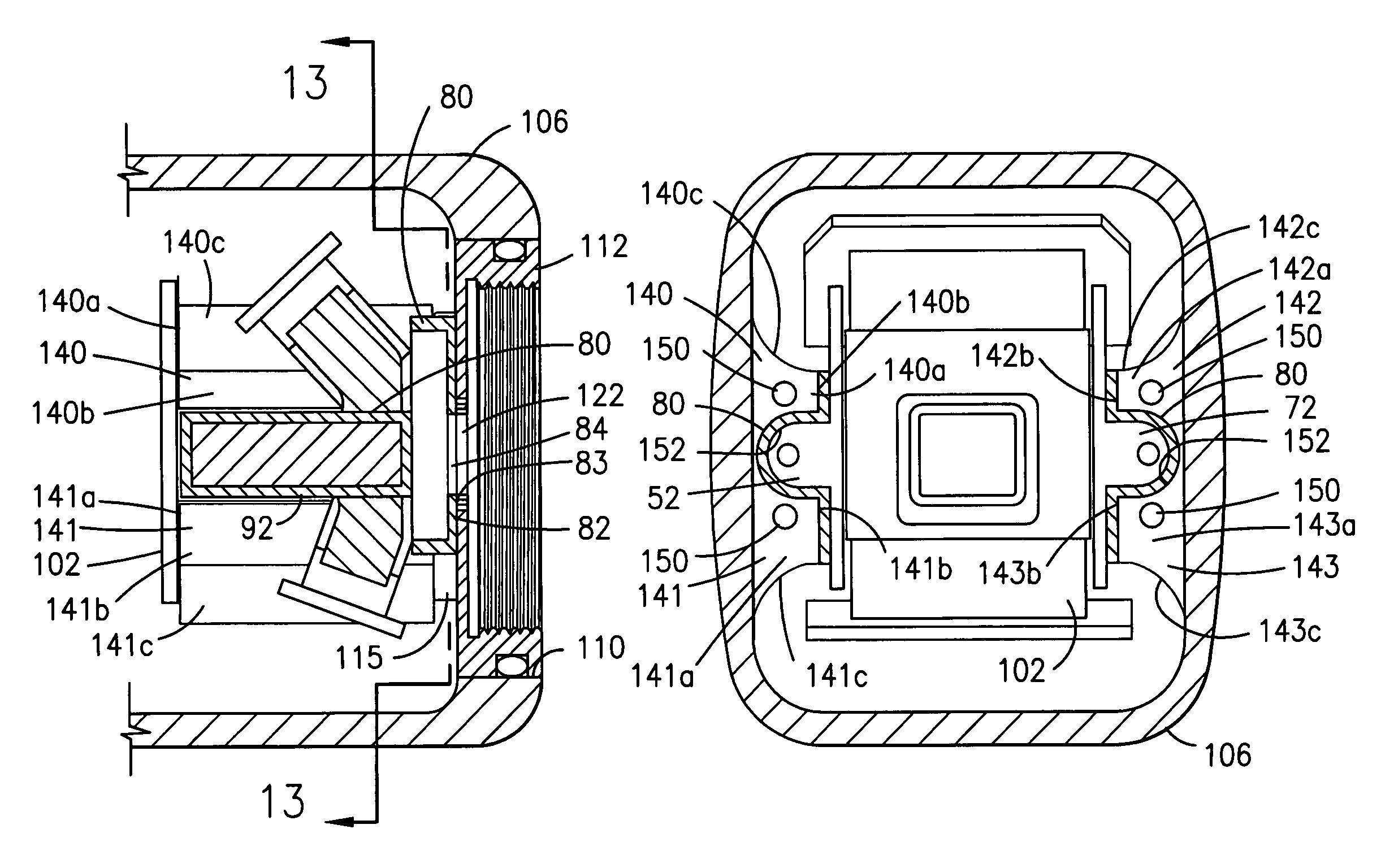
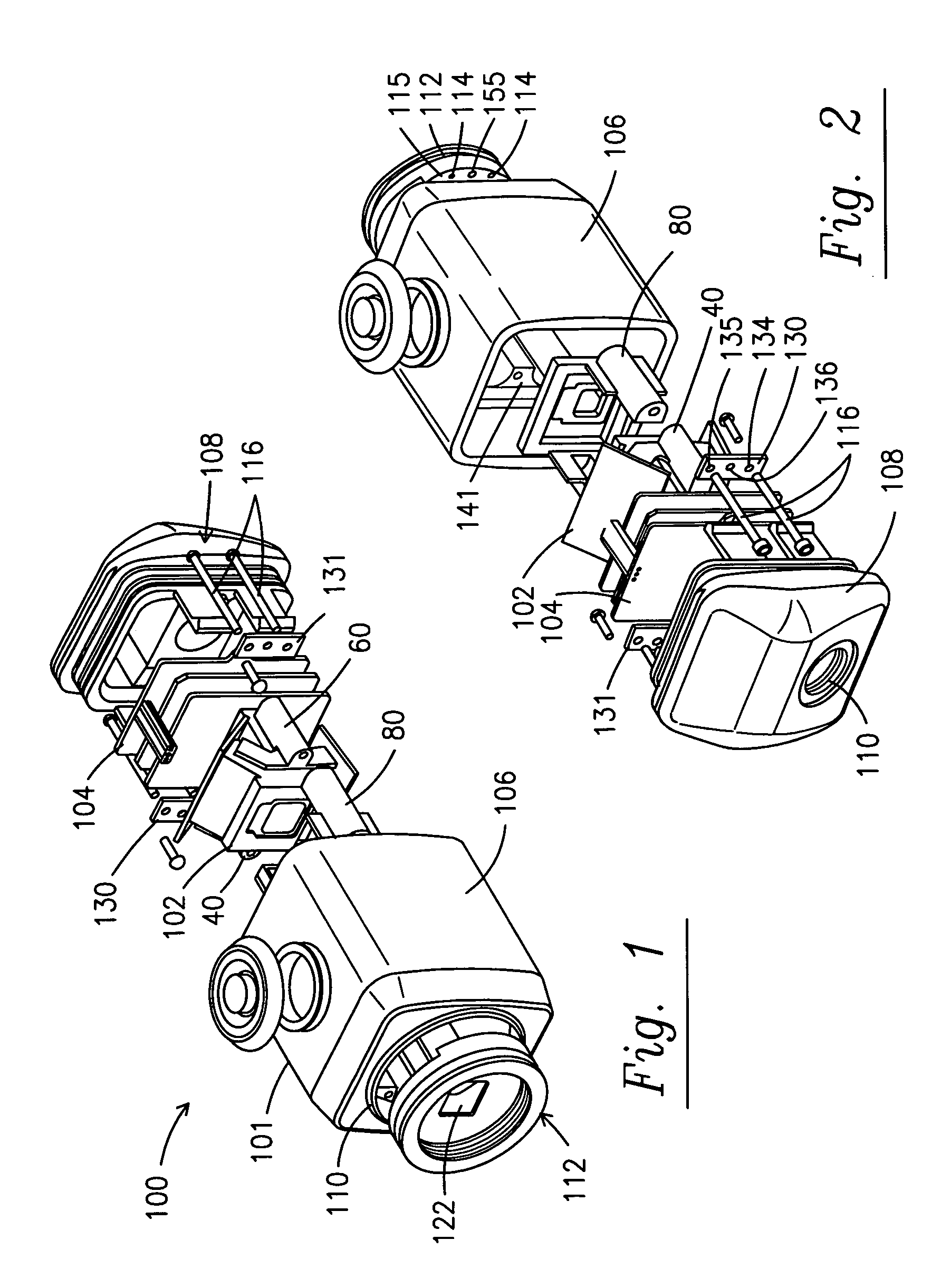
[0025]A representative 3-chip camera constructed in accordance with the principles of this invention is shown in FIGS. 1 and 2. Camera 100 comprises a CCD / prism camera assembly 102 with an associated electronics assembly 104 to operate the camera assembly in a conventional manner (electronics assembly 104 forms no part of this invention). The assemblies 102 and 104 are part of a 3-chip camera produced in a conventional manner which results in a non-ruggedized design. (Part of electronics assembly 104 is not included in the non-ruggedized version of the CCD camera, but is not further discussed here because it forms no part of this invention.) The invention converts this existing camera to a ruggedized version as embodied by camera 100. Camera 100 comprises a housing 101 comprising 4-sided front case 106 to receive the camera assembly and other internal components discussed below, a cover 108 to encase all of the components and help to create a hermetically sealed enclosure and a C-mo...


PUM


Abstract

A shock mounting system for a 3-chip video camera. The system comprises a pair of support plates for spanning the junctions between the various components (prisms, etc.) of a standard charge coupled device (CCD) color camera having 3 CCD's, and an elastomeric boot molded to fit between the CCD camera assembly and the housing within which it is situated. The support plates are made of a material having similar thermal characteristics to the CCD assembly and are suspended within the elastomeric boot.

Description

BACKGROUND OF THE INVENTION[0001]1. Field of the Invention[0002]The invention relates to shock mounting electronic devices. In particular, the invention relates to shock mounting an imaging device used in an endoscopic video camera.[0003]2. Description of the Prior Art[0004]Over the past fifteen years charged coupled device (CCD) video cameras have come into extensive use in industrial and medical fields. In medical applications these cameras attach to an eyepiece of an optical instrument called an endoscope so that one or more physicians observe on a television monitor what one formerly viewed directly by eye at the endoscope eyepiece. With a diameter of generally less than 10 mm, endoscopes are passed into body cavities through small holes to observe structures and perform procedures previously requiring large surgical openings. Two of the most common types of CCD cameras that are in use in medical surgery today are the single CCD camera and the 3-CCD camera, the latter sometimes ...

Claims


Application Information

Patent Timeline
IPC IPC(8): H04N5/225
CPCH04N5/2252H04N5/2253H04N23/51H04N23/54
Inventor WALLS, ROBERT R.
Owner LINVATEC
Why Eureka
Try Eureka