Compact solid-state variable optical delay line with a large continuous tuning range

a variable and solid-state technology, applied in the field of variable optical delay lines, can solve the problems of limiting the achievable accuracy of delay time, difficult cutting fibers to a precision of millimeters, and large dynamic range of variable delay lines

Inactive Publication Date: 2005-10-18
ALCATEL-LUCENT USA INC +1
View PDF4 Cites 21 Cited by
  • Summary
  • Abstract
  • Description
  • Claims
  • Application Information

AI Technical Summary

Problems solved by technology

Variable delay lines are needed because different delays may be required at different times. In addition to variation required by the dynamics of optical network components, variation of delays in the optical network may be required to compensate path length differences in RF links in the network such as differences due to changes in a satellite orbit, due to the use of multiple ground antennas, or due to atmospheric scintillation or beam squinting.
Cutting fibers to a precision of millimeters is difficult, and this difficulty limits the achievable accuracy of delay time.
Moreover, a variable delay line having a large dynamic range will require many precisely cut fibers.
It is not practical to provide sufficient precisely cut fibers to provide fine delay increments over a large dynamic range.
It is difficult to achieve compact structures of many fibers of different lengths.
In addition is the problem of switching an input signal from one fiber to another.
This may be difficult to achieve in switching a beam from one fiber to a nonadjacent other fiber.

Method used


Image

  • Compact solid-state variable optical delay line with a large continuous tuning range
  • Compact solid-state variable optical delay line with a large continuous tuning range
  • Compact solid-state variable optical delay line with a large continuous tuning range

Examples


example 1

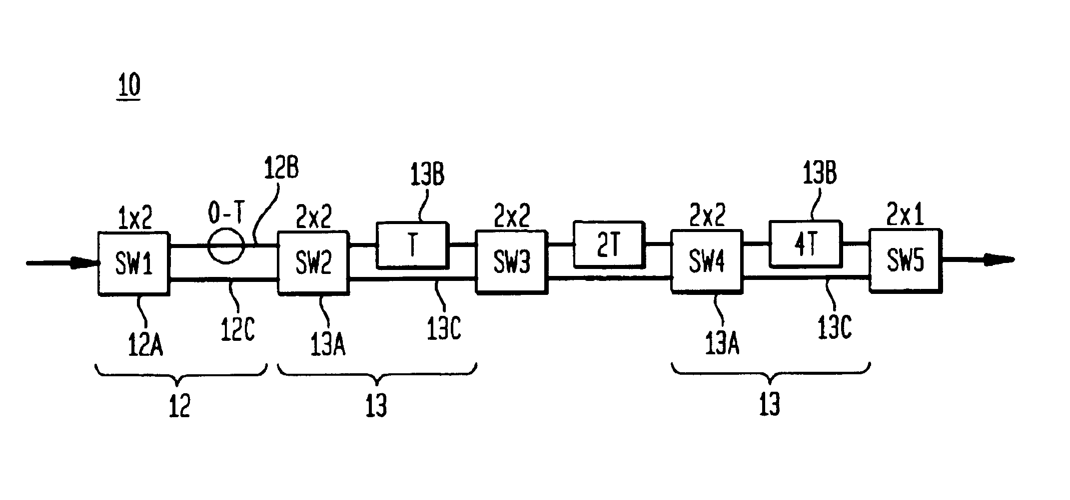
[0025]The layout of FIG. 1 is configured to provide a continuous delay arm APF with T=320 ps. The device thus accommodates a full tuning range of 8T or 2560 ps. Continuous tuning is achieved with the APFs by simultaneous changing two switches between equal path lengths when the APFs are at their maximum delay, after which they are tuned to their minimum delay for the next sub-range. This is the operation set forth in Table 1 where x refers to the cross port configuration and—refers to the bar port. By making two path lengths identical before switching, a coherent switch is achieved that is transparent to an incoming data signal.

[0026]This hitless switching capability is particularly well-suited to implementation in a planar waveguide platform. In glass waveguides, 100 ps corresponds to a length of 2 cm. For a bend radius of 3 mm, a delay length of 2 cm is achieved for each loop. Consequently the longest delay in this example (1280 ps) will require only 13 loops and a very small chip...


PUM

PropertyMeasurementUnit
lengthaaaaaaaaaa
delay lengthaaaaaaaaaa

Abstract

In accordance with the invention, a variable delay line with continuous tuning comprises an optical path providing at least one continuous delay element coupled to a series of switchable binary fixed delays. The series of switchable delays can be configured to select a delay among a plurality of incremental delays, and the continuous delay can set a continuous delay in a range encompassing the delay increment of the binary series. In a preferred embodiment, the variable delay element comprises a tunable all pass filter (APF) with delay tunable from essentially 0 to a time T and the switchable binary fixed delays form a series (0,T), (0, 2T), (0, 4T), . . . , [0, (2n+1)], where n is an integer ≧0. The switches are preferably Mach-Zehnder switches. In an alternative embodiment, the continuous delay element comprises a suitable pair of APF arms. The path and all components can be fabricated as an integrated planar waveguide (solid state) device.

Description

CROSS REFERENCE TO RELATED APPLICATIONS[0001]This case is related to U.S. application Ser. No. 20050031248 filed by J. LeGrange et al. concurrently herewith and entitled “Variable Optical Delay Line With a Large Continuous Tuning Range.”FIELD OF THE INVENTION[0002]This invention relates to variable optical delay lines and, in particular, to a variable optical delay line with continuous tuning and a large tuning range. The delay line is particularly suited for solid state implementation as an integrated optical waveguide device.BACKGROUND OF THE INVENTION[0003]One of the major advances in communications in recent years has been the increased use of optical fiber systems for carrying large quantities of information with low distortion and low cost over great distances.[0004]Optical delay lines are important components in optical fiber communication systems. They are critical components in switching streams of optical signals from one path to another. They are used in packet switching ...

Claims


Application Information

Patent Timeline
Patent Type & Authority Patents(United States)
IPC IPC(8): G02B6/26G02F1/00
CPCG02F1/00G02F2201/20
Inventor MADSEN, CHRISTI KAY
Owner ALCATEL-LUCENT USA INC
Why Eureka
Try Eureka