Method for selection of a receiver tuning frequency

a receiver tuning and frequency selection technology, applied in the field of methods, can solve the problems of instabilities in the tuning of the receiver, the selection of a second transmitter frequency is limited, and the position is very quickly, so as to achieve reliable and stable reception and stabilize the tuning behaviour of the stationary tuner

Inactive Publication Date: 2005-10-18
CONTINENTAL AUTOMOTIVE GMBH
View PDF15 Cites 25 Cited by
  • Summary
  • Abstract
  • Description
  • Claims
  • Application Information

AI Technical Summary

Benefits of technology

[0007]By the measure according to the invention the criteria for selecting a second transmitter are not only based on the reception quality or fieldstrength thereof, but also on the duration or permanency of the reception quality. The longer the reception quality is in excess of said predetermined minimum level, the more reliable and stable the reception of the transmitter signal in question is. By tuning the stationary tuner circuit to such a transmitter, the tuning behaviour of the stationary tuner will be stabilised.
[0008]To allow easy implementation, the method is preferably characterized in that the band scanning search is being repeated in subsequent scan cycles, each detected transmitter increasing respectively decreasing in permanency factor dependent on the detection respectively the absence of detection thereof in subsequent scan cycles.

Problems solved by technology

However, the reception quality measurement is based on the momentary fieldstrength of the RF FM reception signal and the AF having highest fieldstrength at the moment of tuning switch over may lose this position very quickly, due to fluctuations in the environmental reception conditions.
This may cause instabilities in the tuning of the receiver.
Furthermore, in this known receiver, the selection of a second transmitter frequency is limited to the AFs included in the RDS AF list, being alternative frequencies carrying the same audio program as the first transmitter frequency.

Method used


Image

  • Method for selection of a receiver tuning frequency
  • Method for selection of a receiver tuning frequency
  • Method for selection of a receiver tuning frequency

Examples


Embodiment Construction

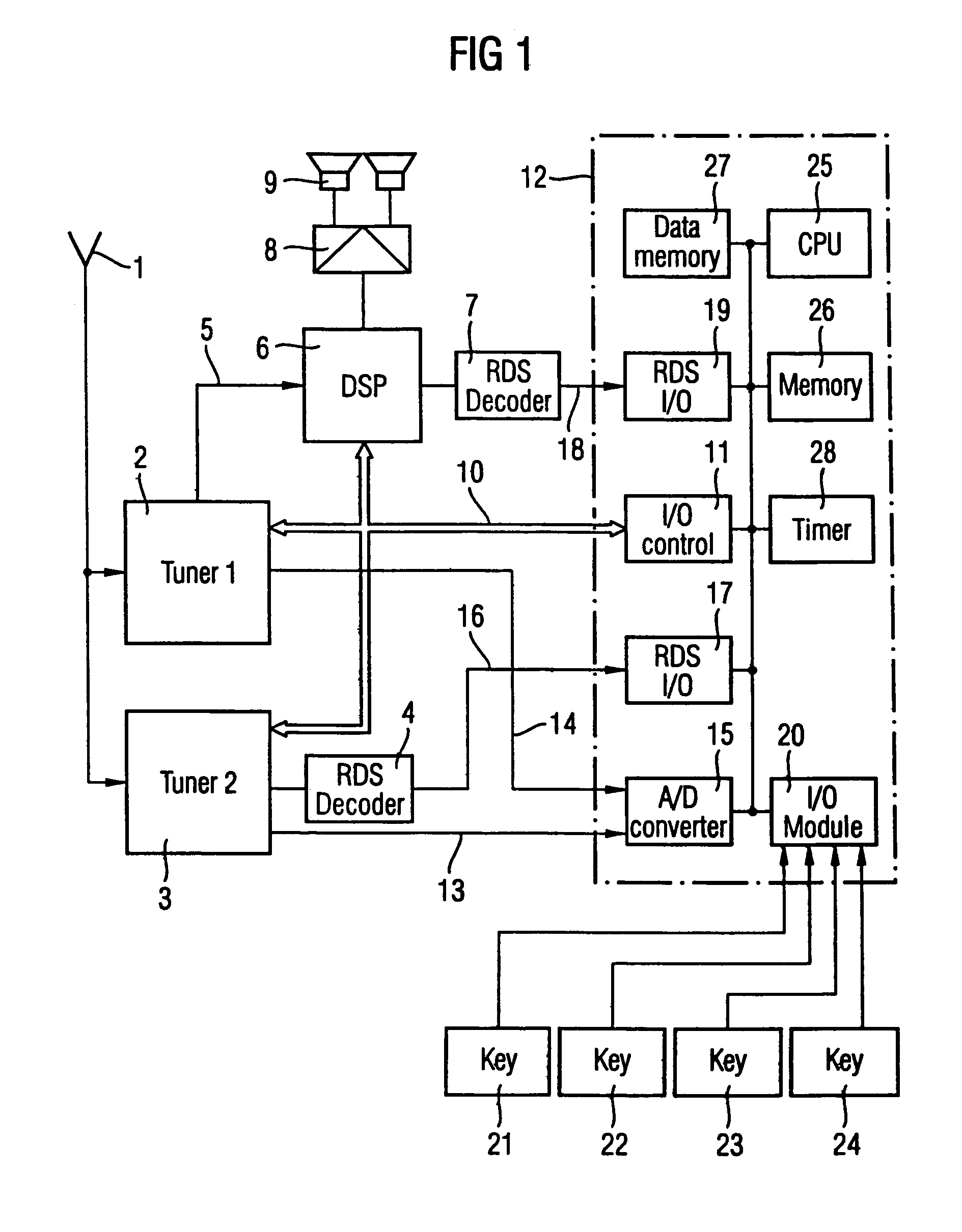
[0022]FIG. 1 shows a blockdiagram of an FM receiver according to the invention, which in the preferred embodiment as shown complies with the FM RDS broadcasting standard as defined in above cited EBU document. Reference is made to this document for detailed information on the meaning and definition of the various terms and abbreviations relating to the RDS standard, as mentioned hereinafter.

[0023]The FM receiver receives RF FM signals through an antenna 1 and following this antenna 1, it comprises first and second tuner circuits 2 and 3, the tuning frequency thereof being controlled from tuning control means 10, 11, 25. The tuning control means 10, 11, 25 comprise a central processing unit (CPU) 25 and an I / O control module 11 being included in a microprocessor 12 and connected through a control bus 10 to the first and second tuner circuits 2 and 3. By manual operation of one of keys 21–24 the tuning frequency of the first tuner circuit 2 can be set through a user interface I / O modu...


PUM


Abstract

Method for tuning the reception of radio broadcast signals to an FM RDS transmitter using program related data and transmitter related data and receiver executing the method, providing a band scanning search for detecting FM RDS transmitters exceeding a predetermined reception quality level. To enhance efficiency in data processing and use of storage capacity, transmitter related data including tuning data is stored separately from program related RDS data. Per each detected transmitter a permanency factor indicating the permanency in reception quality thereof is being allocated to each detected RDS transmitter and stored in a first memory bank, along with the relevant tuning data. Per each program identification code carried in the RDS data of the so detected transmitters program related FM RDS data are being stored in a second memorybank, a linkage code defining the storage address within the second memory bank containing the program data carried by the relevant FM RDS transmitter being allocated to the transmitter data of each FM RDS transmitter and stored in the first memory bank.

Description

FIELD OF THE INVENTION[0001]The invention relates to a method for selecting a tuning frequency for receiving an RF transmitter within an RF frequency band and an FM receiver executing the method.BACKGROUND OF INVENTION[0002]An FM receiver executing the above method is on itself known e.g. from European Patent 0 333 194. The known FM receiver complies with the FM RDS broadcasting standard as defined in Specification of the Radio Data System FM RDS for VHF-FM Sound Broadcasting by the European Broadcasting Union (EBU), EBU document Tech 3244-E, March 1984 and updated in the subsequent revisions thereof. Reference is made to this document for a correct understanding of the meaning and definition of the various terms used hereinafter in connection with the FM RDS standard.[0003]The cited FM receiver comprises a first or stationary tuner circuit and a second or scanning tuner circuit. The stationary tuner circuit is used to tune the receiver to a broadcast transmitter station with a want...

Claims


Application Information

Patent Timeline
Patent Type & Authority Patents(United States)
IPC IPC(8): H03J1/00H03J7/18H03J5/02H04B1/16
CPCH03J1/0083H03J7/186H04H2201/13
Inventor MOERS, PAULUS LOUIS GUIDO
Owner CONTINENTAL AUTOMOTIVE GMBH
Why Eureka
Try Eureka