Control unit for motor-assisted bicycle

a technology of control unit and motor, which is applied in the direction of battery/cell propulsion, process and machine control, instruments, etc., can solve the problems of motor-assisted bicycles of background art that do not provide assist power, and may often fail to suitably generate assist power

Inactive Publication Date: 2005-10-18
HONDA MOTOR CO LTD
View PDF19 Cites 61 Cited by
  • Summary
  • Abstract
  • Description
  • Claims
  • Application Information

AI Technical Summary

Benefits of technology

[0011]An object of the present invention is to provide a control unit for a motor-assisted vehicle allowing the vehicle to be driven wi

Problems solved by technology

Therefore, the motor-assisted bicycles of the background art do not provide an assist power irrespective of the manual power during operation of the vehicle.
The latter-described motor-assisted bicycle of th

Method used


Image

  • Control unit for motor-assisted bicycle
  • Control unit for motor-assisted bicycle
  • Control unit for motor-assisted bicycle

Examples


Embodiment Construction

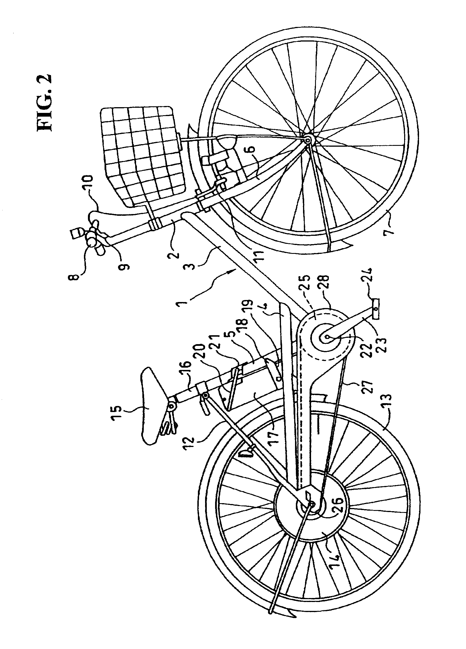
[0041]The present invention will hereinafter be described with reference to the accompanying drawings. FIG. 2 is a side view of a motor-assisted bicycle having the control unit according to an embodiment of the present invention. A body frame 1 of the motor-assisted bicycle includes a head pipe 2 positioned on a front side of a vehicular body, a down pipe 3 extending rearwardly and downwardly from the head pipe 2, a rear fork 4 connected to the down pipe 3 and extending rearwardly therefrom, and a seat post 5 raised from a lowermost end of the down pipe 3.

[0042]A front fork 6 is rotatably supported by the head pipe 2. A front wheel 7 is rotatably supported by lower ends of the front fork 6. A steering handlebar 8 is mounted on an upper end of the front fork 6. A brake lever 9 is provided on the steering handlebar 8. A cable 10 extending from the brake lever 9 is connected to a front wheel brake 11 fixed to the front fork 6. Similarly, while not shown, a brake lever extending to a re...


PUM


Abstract

A control unit for a motor-assisted vehicle such as a bicycle is disclosed that effectively provides an assist drive power to a motor-assisted bicycle during a period of initial pedaling or startup on an upward slope or at the time of acceleration. A first detection signal is outputted when a vehicle speed is equal to or less than a predetermined vehicle speed. A second detection signal is outputted when acceleration is equal to or more than a predetermined value on the basis of a change in the amount of the vehicle speed. A road surface inclination is determined from a map on the basis of a ratio between an actual running resistance and a flat road running resistance. A coefficient K is retrieved form the map corresponding to either the first detection signal or the second detection signal to increase the assist power from the map on the basis of the vehicle speed. The coefficient K is inputted into an assist power calculating portion, and the required assist drive power is calculated.

Description

CROSS-REFERENCES TO RELATED APPLICATIONS[0001]This nonprovisional application claims priority under 35 U.S.C. § 119(a) on Patent Application No. 2001-055399 filed in Japan on Feb. 28, 2001; Patent Application No. 2001-055400 filed in Japan on Feb. 28, 2001; Patent Application No. 2001-055401 filed in Japan on Feb. 28, 2001; and Patent Application No. 2001-055402 filed in Japan on Feb. 28, 2001, the entirety of each of which is herein incorporated by reference.BACKGROUND OF THE INVENTION[0002]1. Field of the Invention[0003]The present invention relates to a control unit for a motor-assisted bicycle, and more particularly to a control unit for driving a motor-assisted bicycle with the same running sensation as that obtained by a bicycle without a motor-assisted unit (hereinafter, referred to as “ordinary bicycle”).[0004]2. Description of the Background Art[0005]A motor-assisted bicycle of a type including a manually powered drive system for transmitting a force applied to pedals by ma...

Claims


Application Information

Patent Timeline
IPC IPC(8): B62M23/02B62M6/45B62M6/65
CPCB60L11/1803B62M6/45B60L11/007B62M6/65B60L2200/12Y02T10/7005Y02T10/7258B60L50/20B60L50/51B62J45/4152Y02T10/70Y02T10/72B60L15/20
Inventor HATANAKA, KAORUFURUTA, SHINJI
Owner HONDA MOTOR CO LTD
Why Eureka
Try Eureka