Upright vacuum cleaner with spring loaded nozzle

a vacuum cleaner and spring-loaded technology, which is applied in the direction of vacuum cleaners, suction filters, cleaning filter means, etc., can solve the problems of affecting the cleaning efficiency of the vacuum cleaner, the tendency of vibration to develop in the vacuum cleaner, and annoying the user, so as to dampen vibration and enhance cleaning efficiency

Inactive Publication Date: 2005-10-25
PANASONIC OF NORTH AMERICA
View PDF19 Cites 13 Cited by
  • Summary
  • Abstract
  • Description
  • Claims
  • Application Information

AI Technical Summary

Benefits of technology

[0007]In accordance with the purposes of the present invention as described herein, an improved upright vacuum cleaner is provided. That vacuum cleaner includes a nozzle assembly and a canister assembly pivotally mounted to the nozzle assembly. A suction fan and motor are carried on one of the nozzle assembly and the canister assembly. Additionally, the upright vacuum cleaner includes a means, such as a biaser, having a first end engaging the nozzle assembly and a second end engaging the canister assembly. This biaser provides a positive downforce urging a forward end of the nozzle assembly toward the surface to be cleaned. This urging not only enhances cleaning efficiency but also serves to dampen vibration.
[0011]The resulting downforce reduces the vibration of the nozzle assembly and advantageously increases the cleaning efficiency of the vacuum cleaner by maintaining the nozzle assembly in close engagement with the surface being cleaned. This is a particular advantage as vibration may even be controlled in canister and nozzle assemblies constructed from lighter weight materials. Such materials allow the production of more lightweight vacuum cleaners that are particularly favored by consumers since they are easier to handle and require less muscle effort to use.
[0012]The invention also includes a method of increasing the cleaning efficiency of a vacuum cleaner by providing a downforce on the nozzle assembly of the vacuum cleaner to urge the nozzle assembly toward the floor being cleaned.
[0013]Still further, the invention also includes a method of reducing vibration in a vacuum cleaner by providing a biasing force between the nozzle assembly and the canister assembly to dampen vibration produced by engagement of the rotary agitator with the surface being cleaned.

Problems solved by technology

This lifting action adversely affects the cleaning efficiency of the vacuum cleaner.
Further, during the cleaning of certain surfaces there is a tendency for vibration to develop in the vacuum cleaner as a result of the engagement of the rotary agitator against the particular surface being cleaned.
This vibration is often transmitted through the control handle and is often annoying to the user.

Method used


Image

  • Upright vacuum cleaner with spring loaded nozzle
  • Upright vacuum cleaner with spring loaded nozzle
  • Upright vacuum cleaner with spring loaded nozzle

Examples


Embodiment Construction

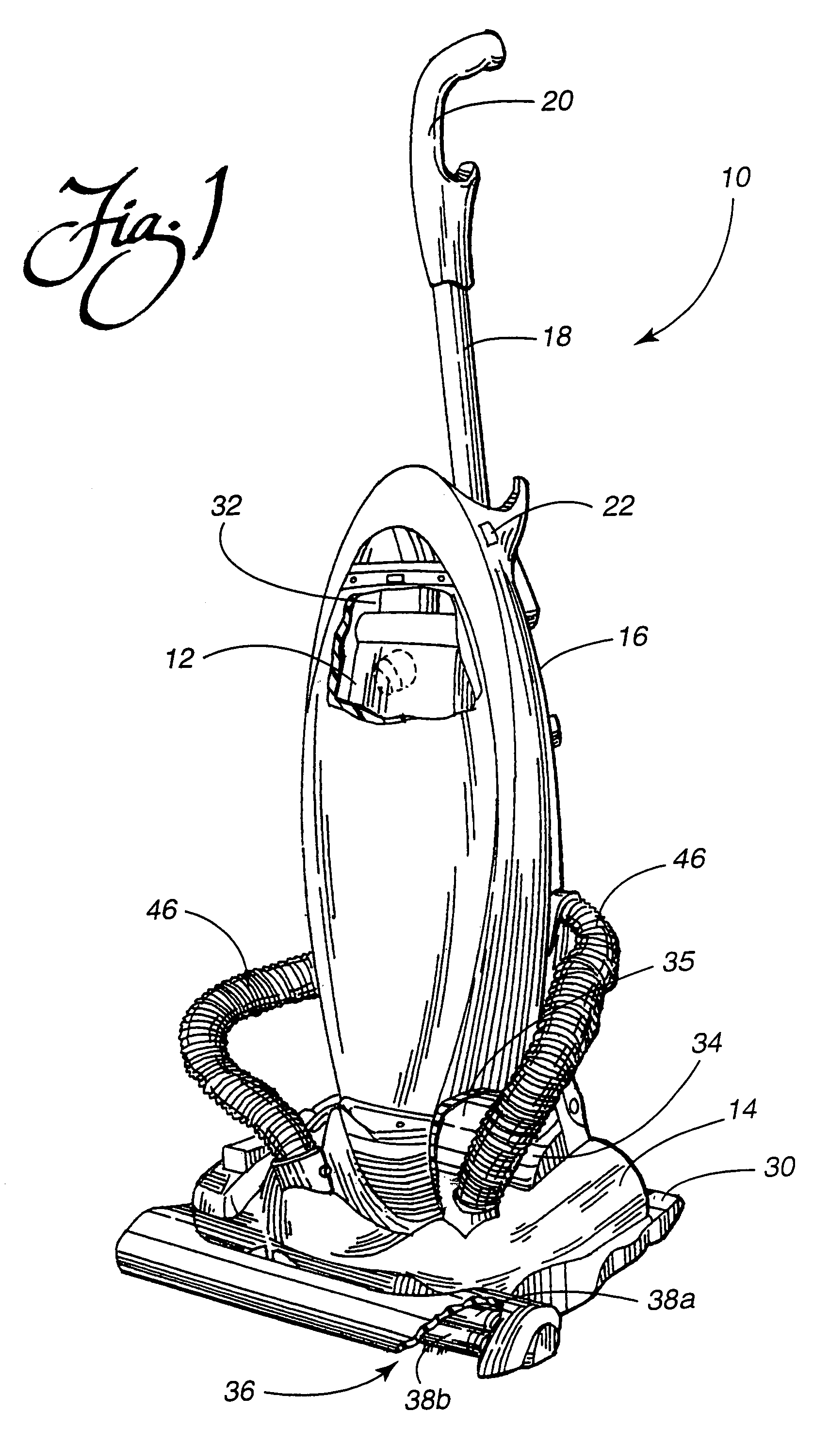
[0021]Reference is now made to FIG. 1 showing the upright vacuum cleaner 10 of the present invention. The upright vacuum cleaner 10 includes a nozzle assembly 14 and a canister assembly 16. The canister assembly 16 further includes a control handle 18 and a hand grip 20. A control switch 22 is provided for turning the vacuum cleaner on and off. Of course, electrical power is supplied to the vacuum cleaner 10 from a standard electrical wall outlet through a cord (not shown).

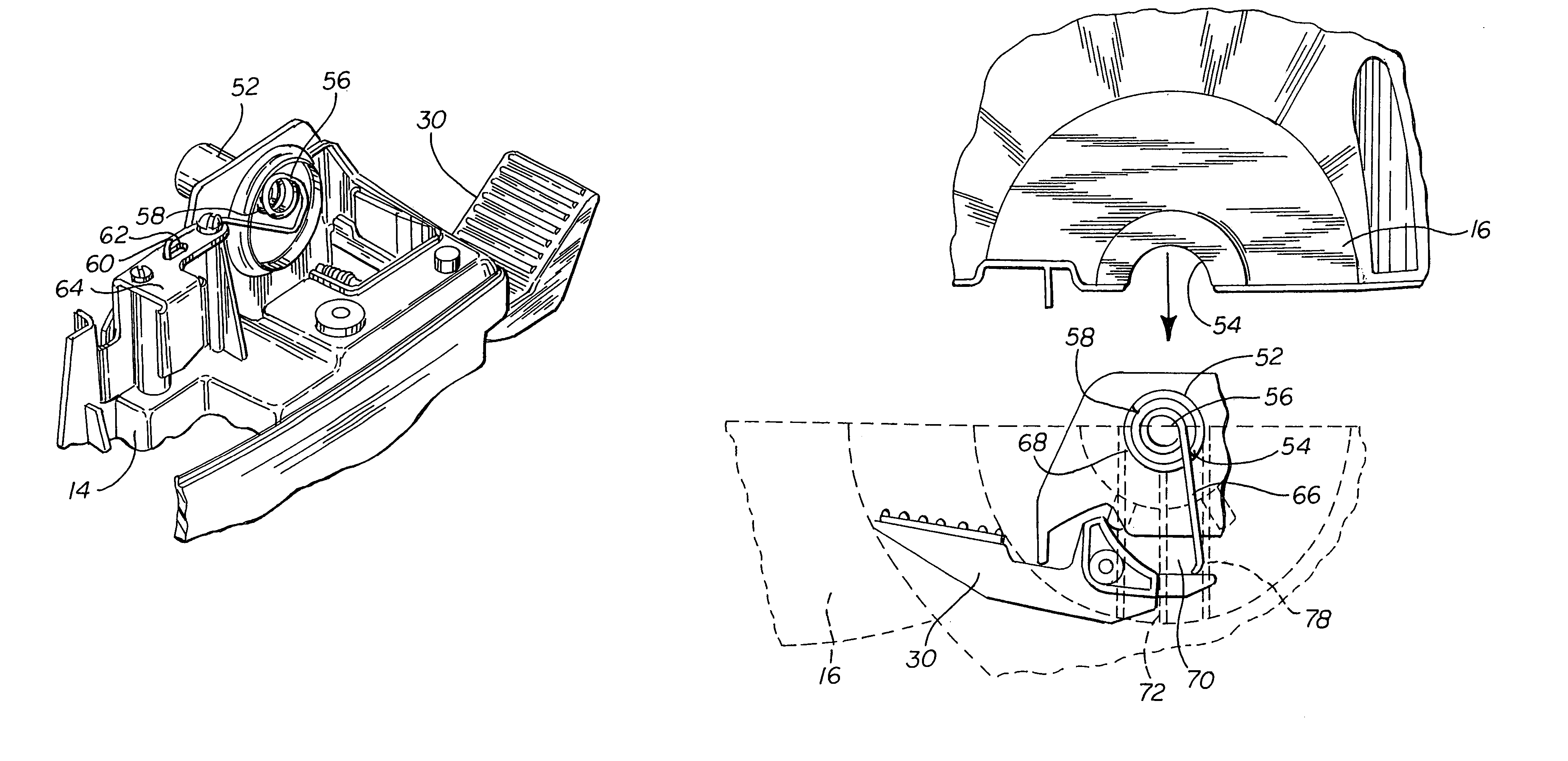
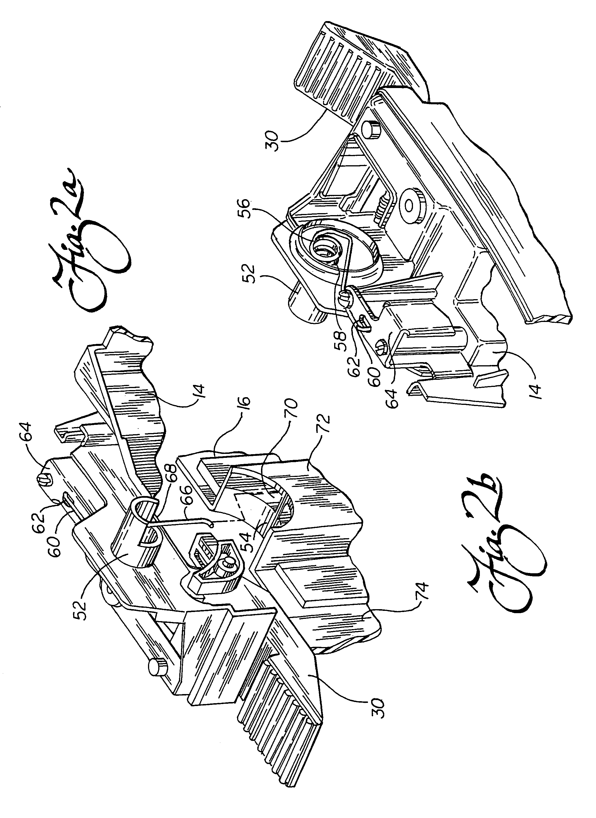
[0022]As is known in the art, sets of front and rear wheels (not shown) are provided, respectively, on the nozzle assembly 14 and canister assembly 16 to support the weight of the vacuum cleaner 10. Together, these two sets of wheels allow the vacuum cleaner 10 to roll smoothly across the surface being cleaned. To allow for convenient storage of the vacuum cleaner 10, a foot latch 30 functions to lock the canister assembly 16 in an upright position as shown in FIG. 1. When the foot latch 30 is released, the canist...


PUM


Abstract

An upright vacuum cleaner includes a nozzle assembly, a canister assembly pivotally mounted to said nozzle assembly, a suction fan and motor and a biaser. The biaser has a first end that engages the nozzle assembly and a second end that engages the canister assembly. The biaser provides a positive downforce urging the forward end of the nozzle assembly toward the surface being cleaned.

Description

[0001]This application is a continuation of U.S. utility patent application Ser. No. 10 / 090,656, filed Mar. 5, 2002 now U.S. Pat No. 6,772,474 which claims the benefit of U.S. Provisional Patent Application No. 60 / 275,065, filed Mar. 12, 2001.TECHNICAL FIELD[0002]The present invention relates generally to the vacuum cleaner art and, more particularly, to an upright vacuum cleaner incorporating a spring loaded nozzle.BACKGROUND OF THE INVENTION[0003]Upright vacuum cleaners in all of their designs and permutations have become increasingly popular over the years. The upright vacuum cleaners generally incorporate a nozzle assembly and a canister assembly pivotally mounted to the nozzle assembly. Wheels on the nozzle and canister assemblies allow the vacuum cleaner to smoothly ride over the surface to be cleaned.[0004]The canister assembly includes an operating handle that is manipulated by the user to move the vacuum cleaner back-and-forth across the floor. The canister assembly also in...

Claims


Application Information

Patent Timeline
Patent Type & Authority Patents(United States)
IPC IPC(8): A47L5/22A47L9/00A47L5/34A47L5/28A47L9/02
CPCA47L5/34A47L9/0081
Inventor NISHIKORI, TAMAKIDAVIS, RON
Owner PANASONIC OF NORTH AMERICA
Why Eureka
Try Eureka