Locking attachment for product display hooks

a technology for locking attachments and product displays, which is applied in the direction of lock applications, washstands, and light support devices, etc., can solve the problems of large loss to merchandisers, serious disadvantages, and high cost of merchandise supported on display hooks, and achieves low cost and large-scale utilization.

Active Publication Date: 2005-10-25
TRION IND
View PDF21 Cites 91 Cited by
  • Summary
  • Abstract
  • Description
  • Claims
  • Application Information

AI Technical Summary

Benefits of technology

[0004]Pursuant to the invention, a novel and improved locking device is provided which is adapted for installation on conventional product display hooks, such that locking devices may be selectively applied in an existing product display, by attaching locks to those hooks containing products likely to be the subject of theft. Significantly, the locking device of the invention can be provided at exceptionally low cost, suitable for large scale utilization by mass merchandisers.

Problems solved by technology

In some cases, the articles of merchandise supported on the display hooks can be of a relatively expensive nature (for example, dry cell batteries).
Historically, the more expensive merchandise items increasingly become the subject of shoplifting, resulting in considerable loss to the merchandiser.
While such arrangements effectively minimize shrinkage losses, they have suffered from serious disadvantages.
Typically, such specially designed hooks have been very costly compared to standard display hooks.
Additionally, installation of the special locking hooks frequently is difficult because of the density of hooks in a typical display panel.
Moreover, after the installation has been completed, the overall product display may look somewhat haphazard because of the variety of hooks involved, with the special locking hooks being interspersed randomly among conventional hooks, in accordance with the location of the expensive product items, in many cases resulting in a relatively unattractive display.

Method used


Image

  • Locking attachment for product display hooks
  • Locking attachment for product display hooks
  • Locking attachment for product display hooks

Examples


Embodiment Construction

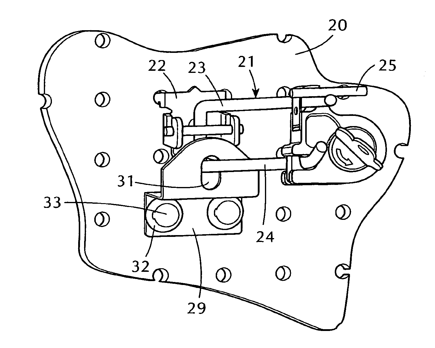
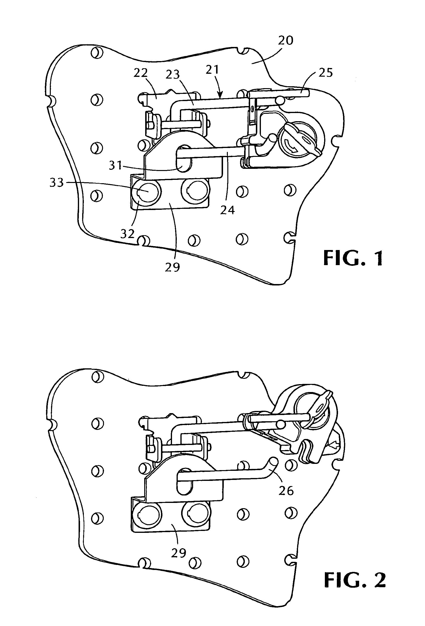
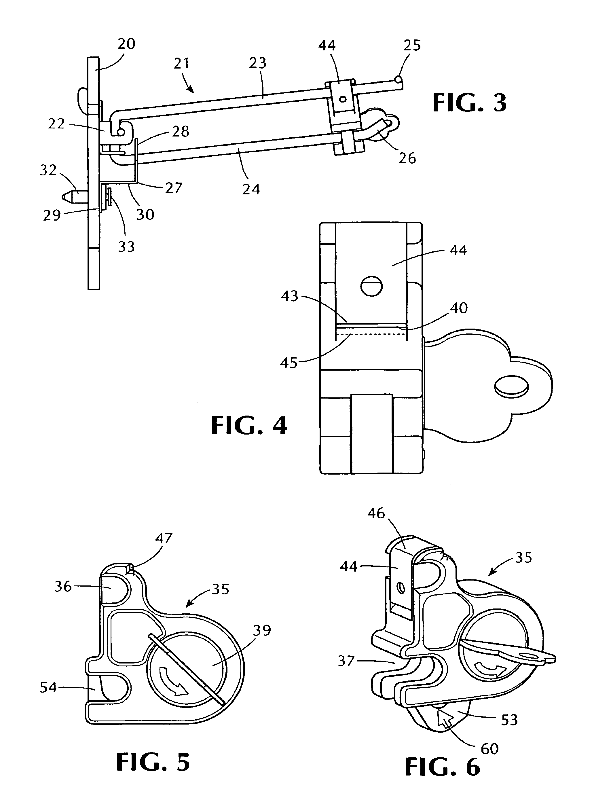
[0023]Referring now to the drawings, and initially to FIGS. 1–3 thereof, the reference numeral 20 designates a typical apertured panel board forming part of a merchandising display. A display hook, which can be of known type, is mounted on the panel board 20. The display hook 21 includes a base member 22 display hook which engages openings in the panel board and mounts upper and lower, outwardly extending wire arms 23, 24. The wire arms 23, 24 advantageously (but not necessarily) are joined as one piece, and the two arms extend outwardly in a generally parallel relationship, as illustrated in FIGS. 1–3.

[0024]The upper arm 23 of the display hook typically is provided with a label holding facility for displaying product pricing and information. In the illustrated arrangement, this is in the form of a welded-on crossbar 25, located at the outer end extremity of the upper wire arm 23. The crossbar 25 is adapted to receive a pivoted label holding element (not shown) with the appropriate ...


PUM


Abstract

A merchandise locking device for retrofit attachment to a product display hook installed on a merchandise display panel. The locking device attaches without tools to the upper wire arm of the display hook for pivoting movement between “lock” and “open” positions. A laterally opening recess in the locking device receives the lower arm of the display hook and a locking arm, rotatably mounted in the body of the locking device by a rotor element, closes the recess to lock the device to the lower arm and prevent the removal of merchandise therefrom. A simple key carried by store personnel enables the rotor to be released to free the locking device from the lower arm and permit the removal of merchandise. The locking device consists of four elements, including the key, and can be manufactured at very low cost, suitable for mass merchandise applications. Simple changes in rotor components enable the locking device to be operated by different keys, which may be color coded with the locking devices or components thereof. A bracket is also provided for retrofit attachment to the display hook, to prevent bodily removal of the hook and its contents from the display panel.

Description

BACKGROUND OF THE INVENTION[0001]Product display hooks are extensively used in connection with the merchandising of products of all types, particularly by mass merchandise chain stores and the like. Typically, product display units, sometimes referred to as gondolas, are formed with a back panel of apertured panel board. The apertured panel board serves as a mounting for a large number of display hooks on which the merchandise is mounted. An advantageous form of display hook is formed of wire and is provided with upper and lower outwardly extending arms. The upper arm mounts a label holder for pricing and other product information, while the lower arm receives the merchandise, typically mounted on cards with openings to receive the projecting wire of the display hook.[0002]In some cases, the articles of merchandise supported on the display hooks can be of a relatively expensive nature (for example, dry cell batteries). Historically, the more expensive merchandise items increasingly ...

Claims


Application Information

Patent Timeline
Patent Type & Authority Patents(United States)
IPC IPC(8): E05B65/00A47F5/00A47F5/08
CPCA47F5/0861Y10T70/5004
Inventor NAGEL, THOMAS O.KOLOGE, JOSEPH F.
Owner TRION IND
Why Eureka
Try Eureka