Exhaust gas recirculation control system

a control system and exhaust gas technology, applied in mechanical devices, electric control, machines/engines, etc., can solve the problems of increased smoke, increased exhaust gas recirculation, so as to reduce the excess air ratio

Active Publication Date: 2005-10-25
NISSAN MOTOR CO LTD
View PDF6 Cites 22 Cited by
  • Summary
  • Abstract
  • Description
  • Claims
  • Application Information

AI Technical Summary

Benefits of technology

[0012]One object of the present invention is to provide an engine exhaust gas recirculation control system that avoids these problems. In other words, the engine exhaust gas recirculation control system of the present invention was basically contrived to avoid to the greatest extent possible the adverse effects on operating performance that can result from hunting of the EGR control when the excess air ratio is reduced.

Problems solved by technology

Therefore, if the opening degree of the intake air throttle valve is suddenly reduced in order to adjust the excess air ratio during regeneration of the NOx trap catalyst, the EGR quantity will increase accordingly and the engine operating performance will degrade, including an increase in smoke.
However, if the opening degree of the EGR valve is feedback controlled, the feedback control will undergo hunting if the opening degree of the EGR valve is corrected in correspondence with the opening degree of the intake air throttle valve because the actual change in the intake air quantity is delayed with respect to the change in the opening degree of the intake air throttle valve.
As a result, vibrations, noise, and other phenomena occur which have an adverse effect on the operating performance.

Method used


Image

  • Exhaust gas recirculation control system
  • Exhaust gas recirculation control system
  • Exhaust gas recirculation control system

Examples


Embodiment Construction

[0020]Selected embodiments of the present invention will now be explained with reference to the drawings. It will be apparent to those skilled in the art from this disclosure that the following descriptions of the embodiments of the present invention are provided for illustration only and not for the purpose of limiting the invention as defined by the appended claims and their equivalents.

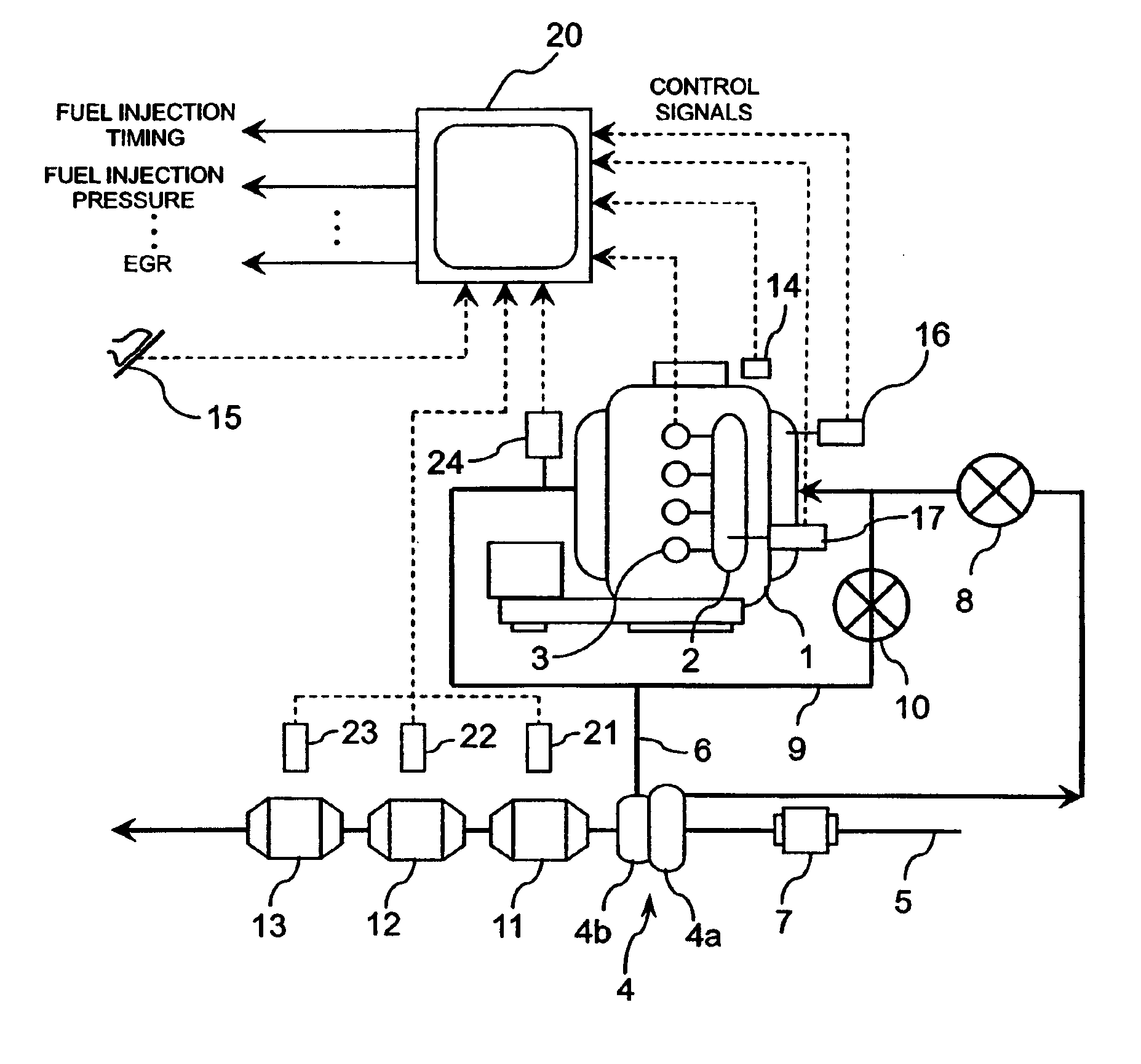
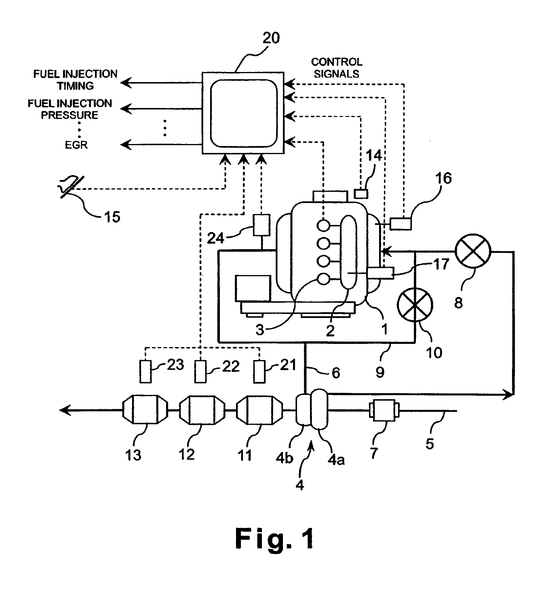
[0021]Referring initially to FIG. 1, an exhaust gas recirculation control apparatus or system is illustrated for an internal combustion engine such as a supercharged diesel engine 1 in accordance with a first embodiment of the present invention. The exhaust gas recirculation control apparatus in accordance with the present invention can be applied to other internal combustion engines used in automobiles and the like.

[0022]As shown in to FIG. 1, the engine 1 includes a common rail fuel injection system including a common rail 2, a plurality of fuel injection valves 3, and a high-pressure fuel pump (...


PUM


Abstract

An engine exhaust gas cleaning apparatus is provided to suppress EGR ratio fluctuations when the excess air ratio is adjusted and thereby stabilize the engine operating performance. The engine exhaust gas cleaning apparatus comprises an exhaust gas recirculation control valve configured to recirculate a portion of the exhaust gas from the exhaust system to the air intake system and feedback control the quantity of the recirculated exhaust; an intake air throttle valve arranged in the air intake system at a position upstream of the position where an exhaust gas recirculation passage connects to the air intake system; an excess air ratio control section configured to change the intake air quantity by using the intake air throttle valve in response to a request to adjust the excess air ratio; and a feedback control restricting section configured to temporarily prohibit feedback control of the exhaust gas recirculation quantity delivered by the exhaust gas recirculation control valve, or to temporarily lower the gain of the feedback control, when the excess air ratio is being adjusted.

Description

BACKGROUND OF THE INVENTION[0001]1. Field of the Invention[0002]The present invention generally relates to exhaust gas recirculation control apparatuses for internal combustion engines. More specifically, the present invention relates to an exhaust gas recirculation apparatus that regenerates an exhaust gas cleaning device by changing the excess air ratio.[0003]2. Background Information[0004]In internal combustion engines such as diesel engines, an exhaust gas recirculating system (EGR system) is widely used wherein a part of the exhaust gas is recirculated to lower the combustion temperature in order to reduce discharge of nitrogen oxide (NOx). A NOx trapping catalytic converter traps NOx in the exhaust gas when an air-fuel ratio in the exhaust gas is in a lean range and purifies (releases) the trapped NOx when the air-fuel ratio is in a rich range. The NOx deposited in the NOx trapping catalytic converter is typically purified when the amount of adsorbed and held NOx reaches a pre...

Claims


Application Information

Patent Timeline
Patent Type & Authority Patents(United States)
IPC IPC(8): F02D21/00F02D41/00F02D21/08F02B47/00F02B47/08F02D41/14F02M25/07F02D41/04F02D43/00F02D45/00
CPCF02B47/08F02D41/0002F02D41/0052F02D41/0055F02D41/027F02D41/1488F02D2041/0017F02M25/0707F02M25/0709F02M25/0713F02M25/0718F02M25/0727F02M25/0738Y02T10/42Y02T10/47F02M26/05F02M26/06F02M26/10F02M26/15F02M26/23F02M26/33Y02T10/40
Inventor MIURA, MANABU
Owner NISSAN MOTOR CO LTD
Why Eureka
Try Eureka