Proportional solenoid valve and control method therefor

a solenoid valve and proportional technology, applied in the direction of transducers, fluid pressure control, instruments, etc., can solve the danger of the motion of the valve element becomes unstable, and the self-induced vibration of the valve element is caused, so as to improve the resistance to oscillation, reduce the self-induced vibration range of the valve element, and improve the effect of resistance to oscillation

Inactive Publication Date: 2005-10-25
MITSUBISHI ELECTRIC CORP
View PDF5 Cites 16 Cited by
  • Summary
  • Abstract
  • Description
  • Claims
  • Application Information

AI Technical Summary

Benefits of technology

[0006]The present invention has been made in order to solve the above problems, and is aimed at providing a proportional solenoid valve and a method for controlling the proportional solenoid valve with which it is possible to lower the self-induced vibration range of a valve element and improve resistance to oscillation.
[0007]According to the present invention, the proportional solenoid valve includes a drain-side passage formed by exhaust passage holes whose number is an even number equal to four or more and arranged at regular intervals in a circumferential direction of a valve seat member. As a result, it is possible to lower the self-induced vibration range of a valve element and to improve resistance to oscillation.
[0008]Further, according to the present invention, there is provided a proportional solenoid valve in which the length of a valve guide portion is set so that when the valve element is brought into con

Problems solved by technology

In a conventional proportional solenoid valve having this construction, self-induced vibration of the valve element is caused by operating temperature and disturbances such as pulsation.
In particular, in recent years, due to rising oil temperatures and the like resulting from size reductions in proportional solenoid valve itself and transmissions, and arrangements in tight spaces, there occurs a situation where there is no choice but to perform control up to the temperature range in which the motion

Method used


Image

  • Proportional solenoid valve and control method therefor
  • Proportional solenoid valve and control method therefor
  • Proportional solenoid valve and control method therefor

Examples


first embodiment

[0020]A proportional solenoid valve according to a first embodiment of the present invention is a hydraulic circuit of an electronically controlled automatic transmission for an automobile (hereinafter simply referred to as an “automatic transmission”), and is used to change the operating oil pressure in an operating portion of the automatic transmission.

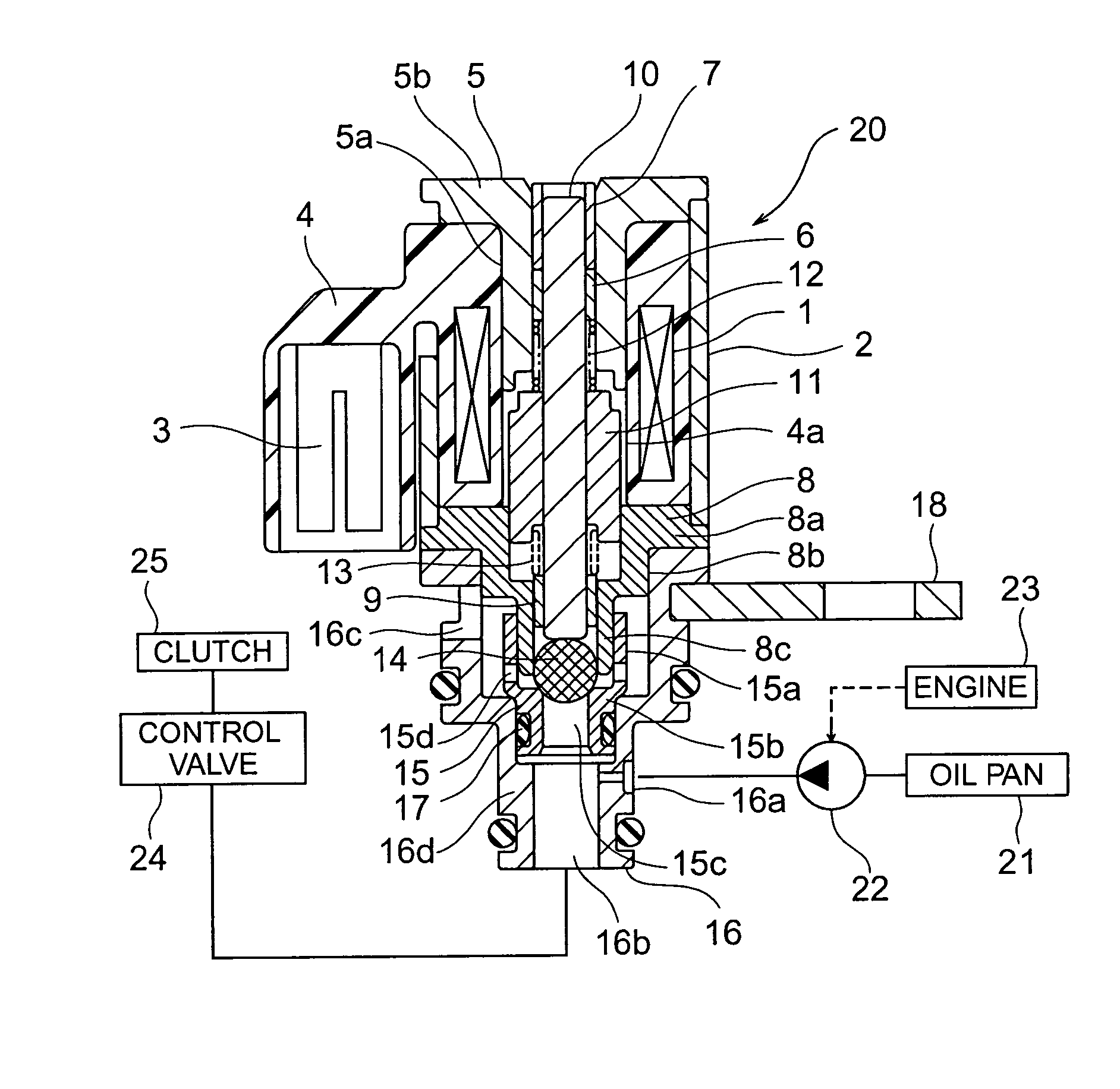
[0021]FIG. 1 is a cross-sectional view of the proportional solenoid valve according to the first embodiment of the present invention. Note that in this drawing, a proportional solenoid valve of normally high type is illustrated. In the drawing, a coil 1 is accommodated in a cylindrical case 2 made of metal and a terminal 3 for connecting the coil 1 to a power supply is arranged outside of the case 2. Further, the coil 1 and the terminal 3 are molded in a resin portion 4 and a plunger accommodating cavity 4a that passes through the hollow portion of the coil 1 while extending in the axial direction of the coil 1 is provided in the re...

second embodiment

[0040]Next, a second embodiment of the present invention will be described. FIG. 5 is a cross-sectional view of the main portion of a proportional solenoid valve according to the second embodiment. In the drawing, the length of the valve guide portion 8c is set so that when the valve element 14 is brought into contact with the seat portion 15b, the tip portion of the valve guide portion 8c protrudes from the center of the valve element 14 towards the seat portion 15b side by 4% to 14% of the diameter of the valve element 14. Other constructions are the same as those in the first embodiment.

[0041]FIG. 6 shows a relationship between the length of the guide tip of the valve guide portion 8c (the length of the protrusion of the tip portion of the valve guide portion 8c from the center of the valve element 14 towards the seat portion 15b side under a state where the valve element 14 is brought into contact with the seat portion 15b) and the self-induced vibration range of the valve eleme...

third embodiment

[0043]Next, a third embodiment of the present invention will be described. FIG. 7 is a cross-sectional view of the main portion of a proportional solenoid valve according to the third embodiment. In the drawing, the input port 16a is provided with an input port orifice 31 and the input / output-side passage 15c is provided with an input / output-side passage orifice 32 having a sectional area that is two to six times as large as the sectional area of the input port orifice 31 (sectional area measured perpendicular to the direction in which the oil flows). Other constructions are the same as those in the first embodiment.

[0044]In such a proportional solenoid valve, since the input port 16a is provided with the input port orifice 31 and the input / output-side passage 15c is provided with the input / output-side passage orifice 32 having a sectional area that is two to six times as large as the sectional area of the input port orifice 31, it becomes possible to lower the self-induced vibratio...


PUM


Abstract

In a proportional solenoid valve, a cylindrical valve seat member includes an input/output-side passage provided between an input port and a drain port and between an output port and the drain port, a seat portion provided in an end portion of the input/output-side passage, and a drain-side passage provided between the seat portion and the drain port. The drain-side passage is formed by exhaust passage holes whose number is an even number equal to four or more and which are arranged at regular intervals in the circumferential direction of the valve seat member.

Description

BACKGROUND OF THE INVENTION[0001]1. Field of the Invention[0002]The present invention relates to a proportional solenoid valve in which a valve element is displaced by applying a current to a solenoid to obtain an output pressure which is proportional to the value of the applied current, and a method for controlling the proportional solenoid valve.[0003]2. Description of the Related Art[0004]In a conventional proportional solenoid valve, a valve element is displaced in accordance with the value of a current applied to a coil while being guided by a cylindrical valve guide portion and is brought into and out of contact with a seat portion, thereby obtaining, from an output port, an output pressure proportional to the value of the applied current (see JP 2002-525524 A, for instance).[0005]In a conventional proportional solenoid valve having this construction, self-induced vibration of the valve element is caused by operating temperature and disturbances such as pulsation. In particula...

Claims


Application Information

Patent Timeline
IPC IPC(8): G05D16/20F16K31/06F16N27/00
CPCF16K31/0665F16N27/00G05D16/2013G05D16/2024Y10T137/0396Y10T137/2278F16K31/06
Inventor TOCHIYAMA, SHIGENOBUONISHI, YOSHIHIKOUNO, SHIGEKINAKAO, KENJI
Owner MITSUBISHI ELECTRIC CORP
Why Eureka
Try Eureka