Latch with bail-type mounting

Inactive Publication Date: 2005-10-25
SOUTHCO
View PDF25 Cites 41 Cited by
  • Summary
  • Abstract
  • Description
  • Claims
  • Application Information

AI Technical Summary

Benefits of technology

[0016]In its application, the inject-eject pawl latch is mounted to a first member, such as a closure panel for releasably retaining the closure panel against an enclosure. More specifically, this panel forms the face of a drawer-type module usually, including an electronic component carrying circuit board. The latch housing can receive a plurality of pins, wherein the handle and pawl members are mounted for rotational movement. The handle is substantially flush with the housing and is in contact with a button member in the closed position. The button releases the pull handl

Problems solved by technology

Previous latches have presented problems that make them difficult or impractical to use to mount and hold removable electronic modules or communications/ power distribution drawers.
Specifically, these latches do not provide an adequate user (operator) finger grasping surface to pull open.
The force necessary to open these latches and thereby disengage an electric

Method used


Image

  • Latch with bail-type mounting
  • Latch with bail-type mounting
  • Latch with bail-type mounting

Examples


second embodiment

[0158]Simultaneously, the remainder of the contact points 192AA, 192BB are secured against the bottom of the panel 32B. The multiple contact points of the clamp 192A, 192AA, 192B, 192BB are used to distribute tension load. In FIGS. 14, 15, 15A through 15E, and 16, the mounting is illustrated, wherein a cradle-type bracket 212 is attached to the housing 102 by any of a variety of attachment means, including self-tapping screws. The attachment screw extends through an aperture 214 in the cradle bracket 212 and a receiving hole in the housing 131. A prepared panel 230 is shown in FIG. 16 to accommodate the bracket 212. The bracket ends 216A, 216B contact the bottom side of the panel 232B, wherein the panel 230 is held in place by the bracket 212, ramps 142A, 142B and the undercuts 151A, 151B. The cutout 234 has 3 notches 234A, 234B and 234C, with the first to on opposite sides and the third at one end.

[0159]In FIGS. 17 through 19, the activation of the latch 100 and ejection of the mod...

first embodiment

[0168]As shown in FIGS. 26 and 26A through 26E, the handle 508 has a body portion 574 with a flat top surface 574A and a contoured bottom surface 574B which converge forward to form a pawl 504. The bottom surface of the handle 574B has a groove 575 wherein the torsion spring 510 is aligned to retard movement when the latch 500 is assembled. As in the first embodiment, the body portion 574 is interrupted midway by a top aperture 584 which allows access to the button member 506. The bottom surface 574A of the body portion 574 extends into the aperture 584 so as to form a lip portion 586.

[0169]As shown in FIGS. 27 and 27A, the continuous flat spring 511 has a hairpin coil 511A and a obtuse coil 511B. The function of the hairpin coil 511A is for mounting on the spring mount 530A wherein the function of the obtuse coil 511B is biasing the movement of the housing 502 when in the panel as will be discussed further below.

[0170]FIGS. 28 and 28A show the torsion spring has a closed end 588 wh...

third embodiment

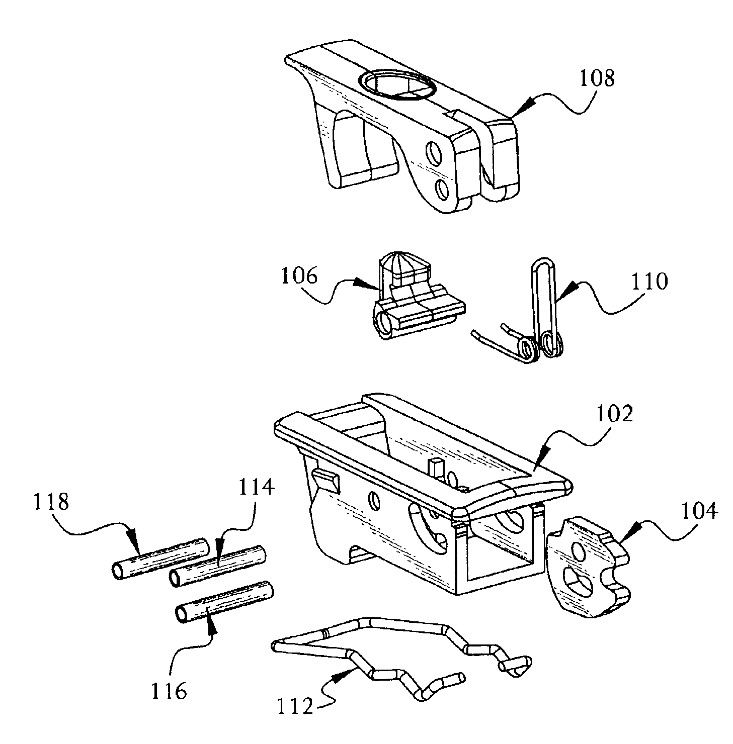
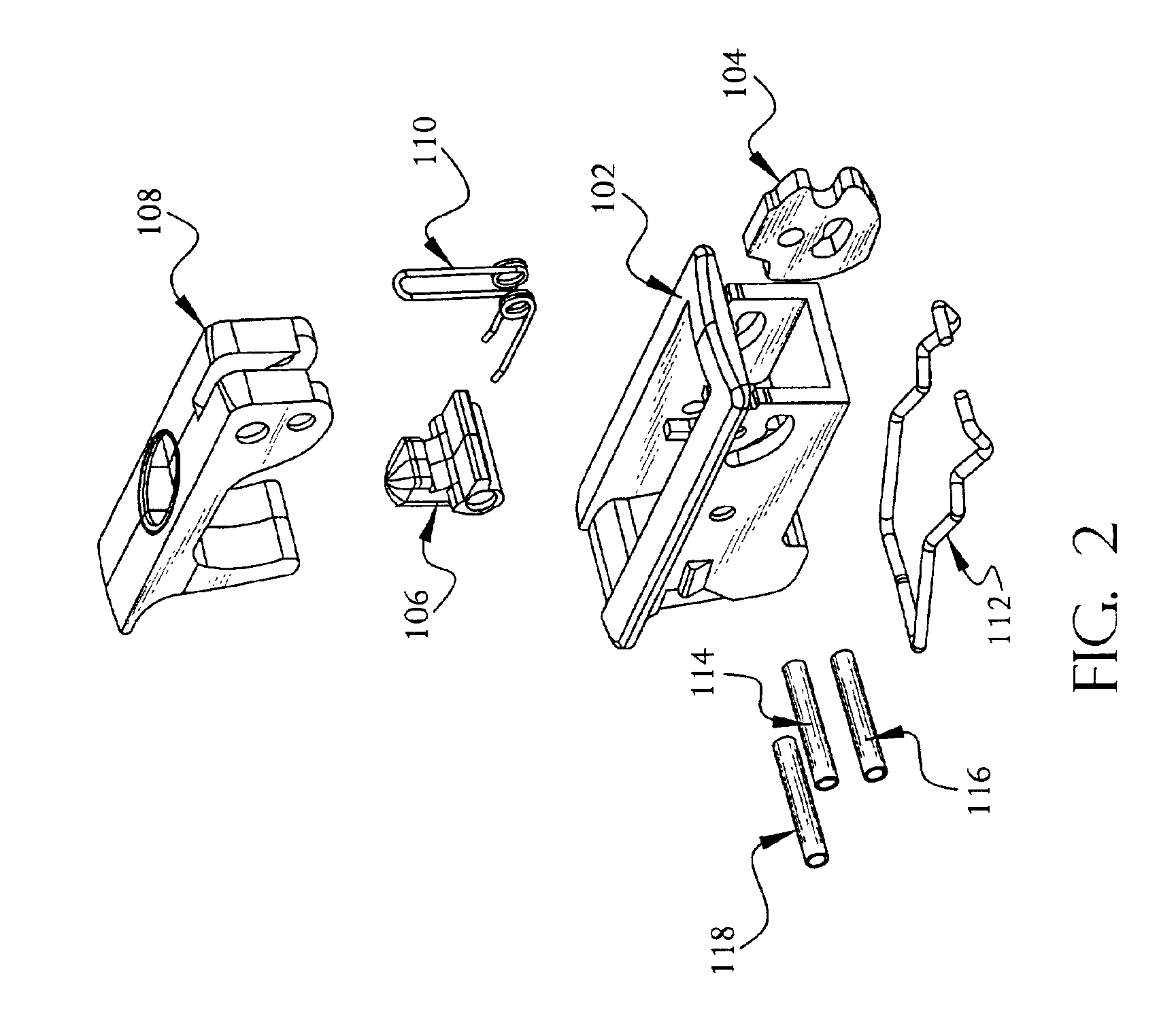
[0174]Referring to FIGS. 35, 35A through 35E, and 36, the third embodiment latch 700 in the closed position. This latch 700 includes a housing 702, a pawl member 704, a button member 706, a handle 708, a torsion spring 710, and pin members 714, 716, 718 and 719. The pawl member has a longitudinal aperture 756 and an rear aperture 754 which are shaped so as to limit the rotation of the handle 708 after disengagement from the button member 706.

[0175]Shown in FIGS. 37 to 41, latch 700 activation is accomplished as in the preferred embodiment 100 and the second embodiment 500 wherein the button member 706 disengages the handle member 708. The latch 700 is driven by the torsion spring 710 to a first position as guided by the shape of the longitudinal pawl member 756. The forward pin member 716 is stopped at the first curved portion 756A. Further rotation by the operator will bring the forward pin member 716 to the second curved portion 756B wherein it will stop until further rotation by ...


PUM


Abstract

The present invention is a pawl latch which is adapted to be mounted to a first member, such as a closure panel of drawer face plate for releasably retaining the closure panel against an enclosure. Such drawer is suitable for implementing an electronic module which plugs into the backplane of the enclosure. The latch has spring-assisted engagement and disengagement of its pawl with the edge of an enclosure opening against which the pawl operates. This results in spring-assisted inject and eject functions for connecting and disconnecting any associate backplane connection. The latch is low profile with a narrow footprint and has an EMI and ESD event preventive coating on the surface of the housing and appropriate components thereof. A pull handle is substantially flush with the outside face of the latch housing and cooperates with a button spring activator member, when the handle is in the closed position.

Description

RELATED APPLICATIONS[0001]The subject matter of this application relates to the invention disclosed in, and claims benefit of, U.S. Provisional Application No. 60 / 295,179, titled, Pawl Inject / Eject Latch, filed Jun. 1, 2001, and U.S. Provisional Application No. 60 / 371,527, titled, Sliding Panel Latch, filed Apr. 9, 2002.BACKGROUND OF THE INVENTION[0002]This invention relates generally to a latch for releasably securing a first member relative to a second member. The first member moves at least partially relative to the second member resulting in a secured position.[0003]Latches are used to releasably secure panels, covers, doors, drawers, electronic modules, glove boxes, and the like to other generally larger structures, such as housings, compartments, doorframes, panel fronts, frames, racks and other structures. These latches are mounted by various means, including screws, rivets, blade fasteners, spring clips, stake fasteners and other structures. Each latch generally includes a h...

Claims


Application Information

Patent Timeline
IPC IPC(8): H05K7/14
CPCH05K7/1409
Inventor WELSH, THOMAS W.BUCCI, MICHAEL S.SCHLACK, RICHARD E.
Owner SOUTHCO
Why Eureka
Try Eureka