Low power thermoelectric generator

a low-power, generator technology, applied in the direction of thermoelectric devices, machine operation modes, lighting and heating apparatus, etc., can solve the problems of reducing the repeatability of the device, requiring numerous manufacturing steps, and discharging the power supplied by the battery. to achieve the effect of enhancing the repeatability

Inactive Publication Date: 2005-10-25
DIGITAL ANGEL CORP
View PDF25 Cites 30 Cited by
  • Summary
  • Abstract
  • Description
  • Claims
  • Application Information

AI Technical Summary

Benefits of technology

The patent describes a design for a foil segment that has thermoelectric legs on its surface. These foil segments are arranged in a way that their back surface faces the front surface of an adjacent foil segment. The foil segments are made of a material called thermoelectric, which has a thickness of about 5 to 100 μm. The front surface of the foil segment is smoother than the back surface to improve the accuracy of forming the thermoelectric legs. This design can help improve the performance of the foil segments in applications such as thermometers or heat exchangers.

Problems solved by technology

The present invention is about a new thermoelectric generator that is small and can produce a high output voltage. The problem that this invention solves is the need for a self-sufficient power source for microelectronic devices that is also cost-effective and easy to manufacture. The invention uses a new design that is compact and efficient, with a high output voltage to power small devices like wristwatches. Previous methods of thermoelectric generators have either required large areas or been costly to manufacture. The invention is also adaptable to different temperature differences between hot and cold sides, making it suitable for various applications.

Method used


Image

  • Low power thermoelectric generator
  • Low power thermoelectric generator
  • Low power thermoelectric generator

Examples


Embodiment Construction

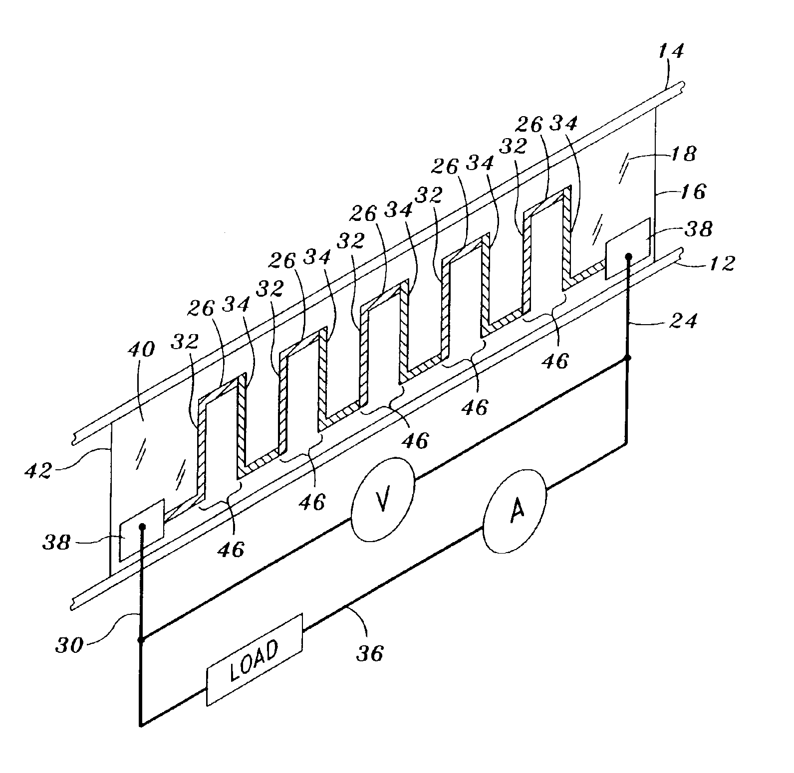
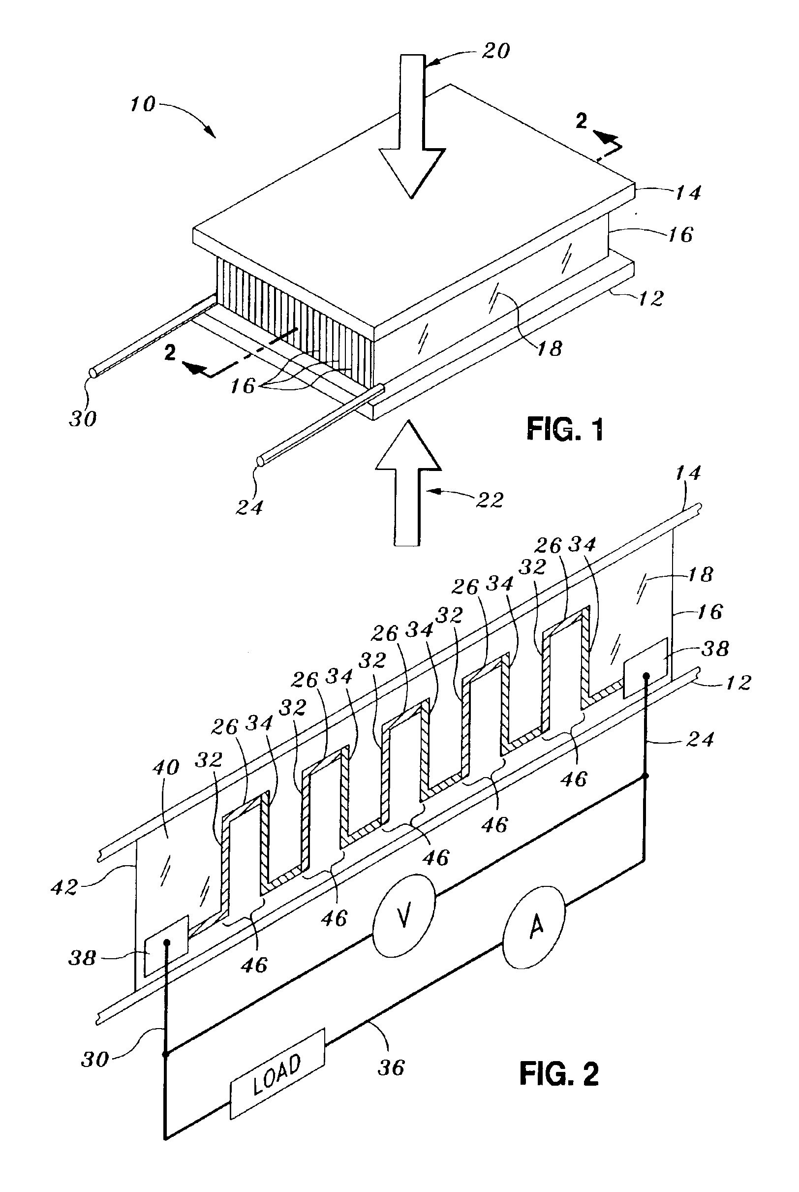
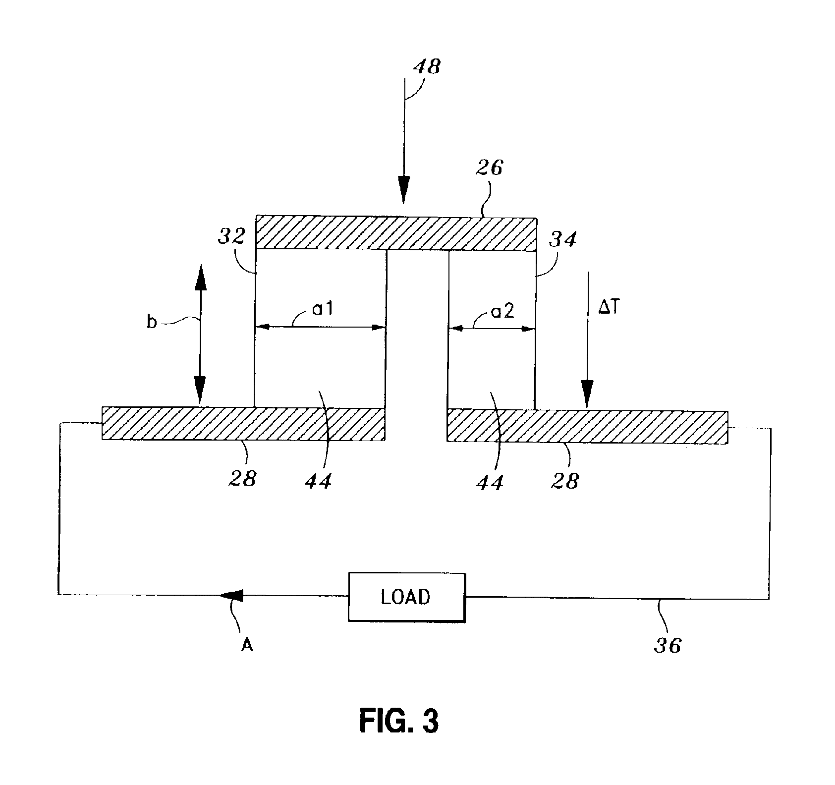
[0027]Referring now to the drawings wherein the showings are for purposes of illustrating preferred embodiments of the present invention and not for purposes of limiting the same, FIG. 1 is a perspective view of the thermoelectric generator 10 within which a foil segment 16 of the present invention may be utilized. As mentioned above, the thermoelectric generator 10 takes advantage of a thermal gradient to generate useful power according to the Seebeck effect. The thermoelectric generator 10 is typically comprised of a bottom plate 12, a top plate 14, and an array of foil segments 16. The array of foil segments 16 are interposed between the bottom plate 12 and the top plate 14 in side-by-side arrangement, with each one of the foil segments 16 being perpendicularly disposed between and in thermal contact with the bottom and top plates 12, 14. A series of generally elongate, alternating n-type and p-type thermoelectric legs 32, 34 is disposed on a substrate 18 of each one of the foil ...


PUM


Abstract

Disclosed is a foil segment for a thermoelectric generator comprising a top plate disposed in spaced relation above a bottom plate. An array of the foil segments is perpendicularly disposed in side-by-side arrangement between and in thermal contact with the bottom and top plates. Each foil segment comprises a substrate having a thickness of about 7.5-50 microns, opposing front and back substrate surfaces and a series of spaced alternating n-type and p-type thermoelectric legs disposed in parallel arrangement on the front substrate surface. Each of the n-type and p-type legs is formed of a bismuth telluride-based thermoelectric material having a thickness of about 5-100 microns, a width of about 10-100 microns and a length of about 100-500 microns. The alternating n-type and p-type thermoelectric legs are electrically connected in series and thermally connected in parallel such that a temperature differential between the bottom and top plates results in the generation of power.

Description


Claims


Application Information

Patent Timeline
Owner DIGITAL ANGEL CORP
Why Eureka
Try Eureka