Method and apparatus for determining and correcting for illumination variations in a digital projector

a digital projector and illumination variation technology, applied in the field of display devices, can solve problems such as the inability to correct for individual pixel intensity variations, and achieve the effect of low cos

Inactive Publication Date: 2005-10-25
EASTMAN KODAK CO
View PDF27 Cites 6 Cited by
  • Summary
  • Abstract
  • Description
  • Claims
  • Application Information

AI Technical Summary

Benefits of technology

[0005]The method and apparatus of the present invention has the advantage of correcting for each pixel of the display.

Problems solved by technology

One problem with this approach is that the Sheppard et al. device uses a CCD sensor wherein each pixel in the sensor sense

Method used


Image

  • Method and apparatus for determining and correcting for illumination variations in a digital projector
  • Method and apparatus for determining and correcting for illumination variations in a digital projector
  • Method and apparatus for determining and correcting for illumination variations in a digital projector

Examples


Embodiment Construction

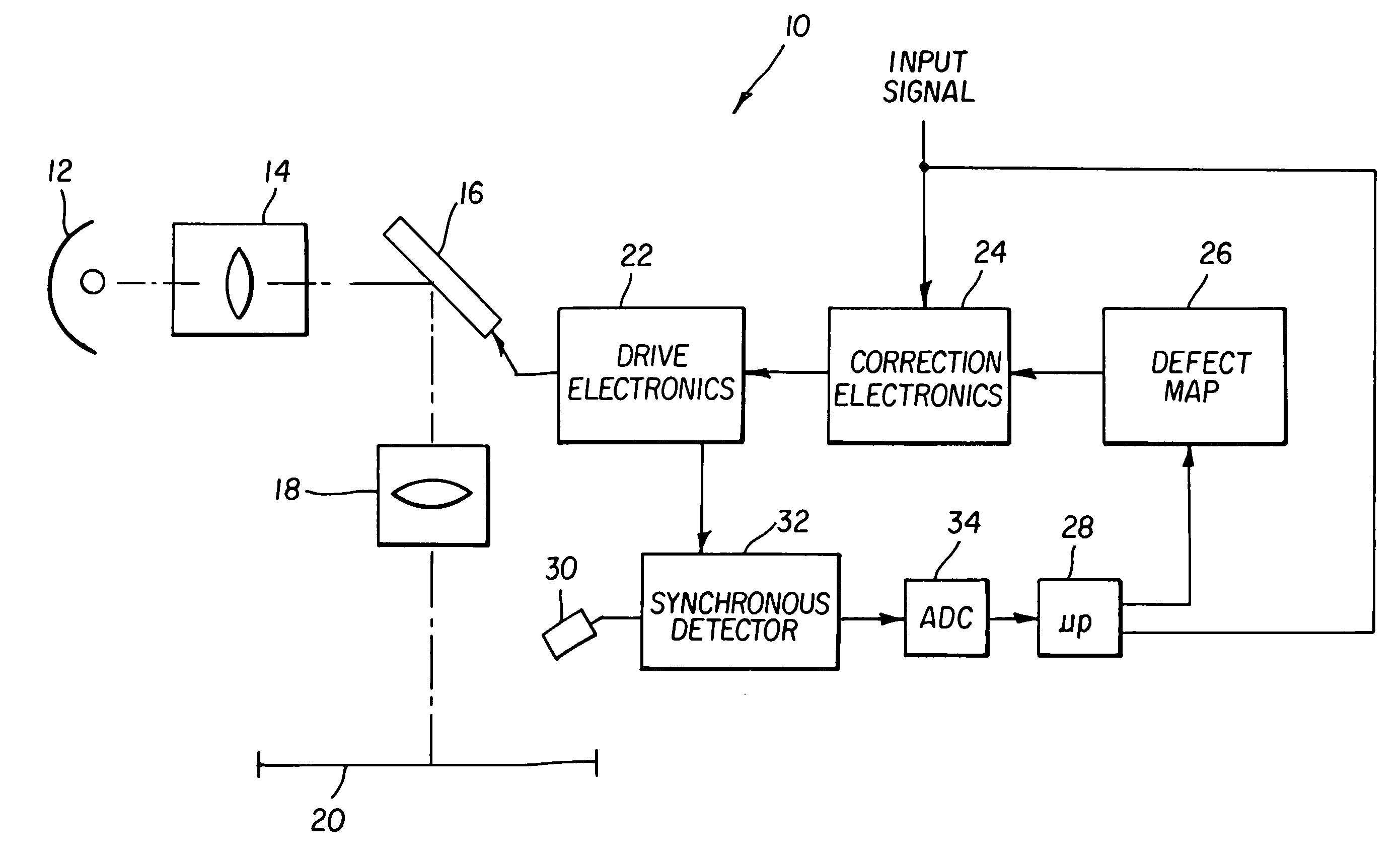
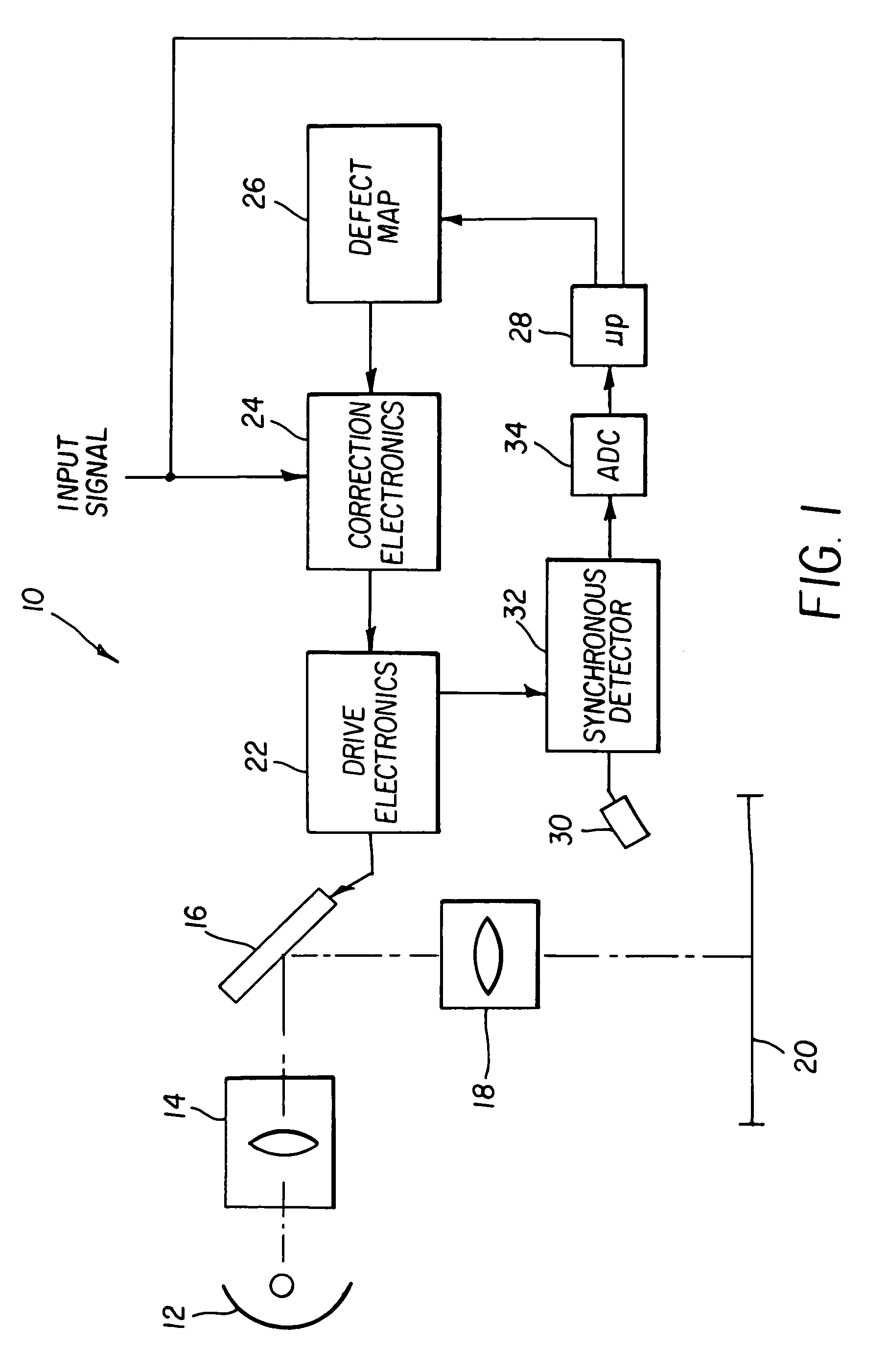
[0010]The present invention collects data on pixel gain and intensity using a simple sensor that collects light from the entire projected image. To obtain the correction data, all pixels are driven to black, or a predetermined level except for the pixel under observation. The pixel under observation is driven at a predetermined frequency that is preferably some fraction of the refresh rate of the display. A photosensor senses the entire display to produce a signal representing the light from the pixel. To increase sensor accuracy according to the present invention, the sensor is equipped with a synchronous demodulator that demodulates the signal at the predetermined frequency. The sensed intensity and the predetermined intensity are employed to generate an offset correction. The process is repeated for a plurality of intensities to generate a gain correction. The process is repeated for all pixels of the modulator and correction values created.

[0011]Referring to FIG. 1, a projection...


PUM


Abstract

The need is met according to the present invention by providing a method of correcting pixel by pixel variations in a display, the method including the steps of creating a defect map of pixel intensity offsets for the display; correcting an input signal according to the defect map; and displaying the corrected input signal on the display, wherein the offset defect map is created by modulating a pixel in the display at a predetermined rate at a predetermined intensity; sensing the display with a photosensor to generate a sensed signal; demodulating the signal with a synchronous demodulator at the predetermined rate to produce a demodulated signal representing a sensed intensity; and employing the sensed intensity and the predetermined intensity to generate a correction offset.

Description

FIELD OF THE INVENTION[0001]The present invention relates to display devices, and more particularly to methods and apparatus for correcting for variations in the display devices.BACKGROUND OF THE INVENTION[0002]Digital projection systems can exhibit variations in gain and intensity (offset) from pixel to pixel. These variations can be due to variations in the driving electronics, the light modulator, the projection optics, the display screen, and the illumination optics. Electronic systems can be developed to correct for the variations by applying gain and offset correction values to each pixel. U.S. Pat. No. 6,061,102 issued May 9, 2000 to Sheppard et al. shows a target brightness map that is generated for each of a plurality of preselected shading application points and the target brightness map is used to correct the input signal to the display to remove variations in the display. The shading process is automatically performed during projector setup.[0003]One problem with this ap...

Claims


Application Information

Patent Timeline
IPC IPC(8): H04N5/74H04N5/21
CPCH04N5/74H04N5/21
Inventor ORFITELLI, WILLIAM A.MARKIS, WILLIAM R.
Owner EASTMAN KODAK CO
Why Eureka
Try Eureka