Multi-cell energy conversion device

a multi-cell energy and conversion device technology, applied in the direction of dc-ac conversion without reversal, process and machine control, instruments, etc., can solve the problems of increasing the size of the capacitor of the device, increasing the price and the volume of the device, etc., to reduce the volume, the effect of high voltage level and extending the use field of high-powered conversion devices

Inactive Publication Date: 2005-10-25
INST NAT POLYTECHN DE TOULOUSE 50 PART INTEREST
View PDF4 Cites 14 Cited by
  • Summary
  • Abstract
  • Description
  • Claims
  • Application Information

AI Technical Summary

Benefits of technology

[0013]The invention seeks to remedy these drawbacks of the conventional device described previously by creating a device for reversible conversion of electrical energy which is capable of extending the field of use of high-powered conversion devices towards increasingly high voltage levels whilst permitting a substantial reduction in its volume and retaining the properties of the converter described in the publication EP 0 555 432 which are set out above.

Problems solved by technology

This voltage increase leads indirectly to an increase in the size of the capacitors of the device which have to support increasingly substantial fractions of this voltage.
Also nowadays, above 6 kV the price and the volume of the device tend to become prohibitive.

Method used


Image

  • Multi-cell energy conversion device
  • Multi-cell energy conversion device
  • Multi-cell energy conversion device

Examples


Embodiment Construction

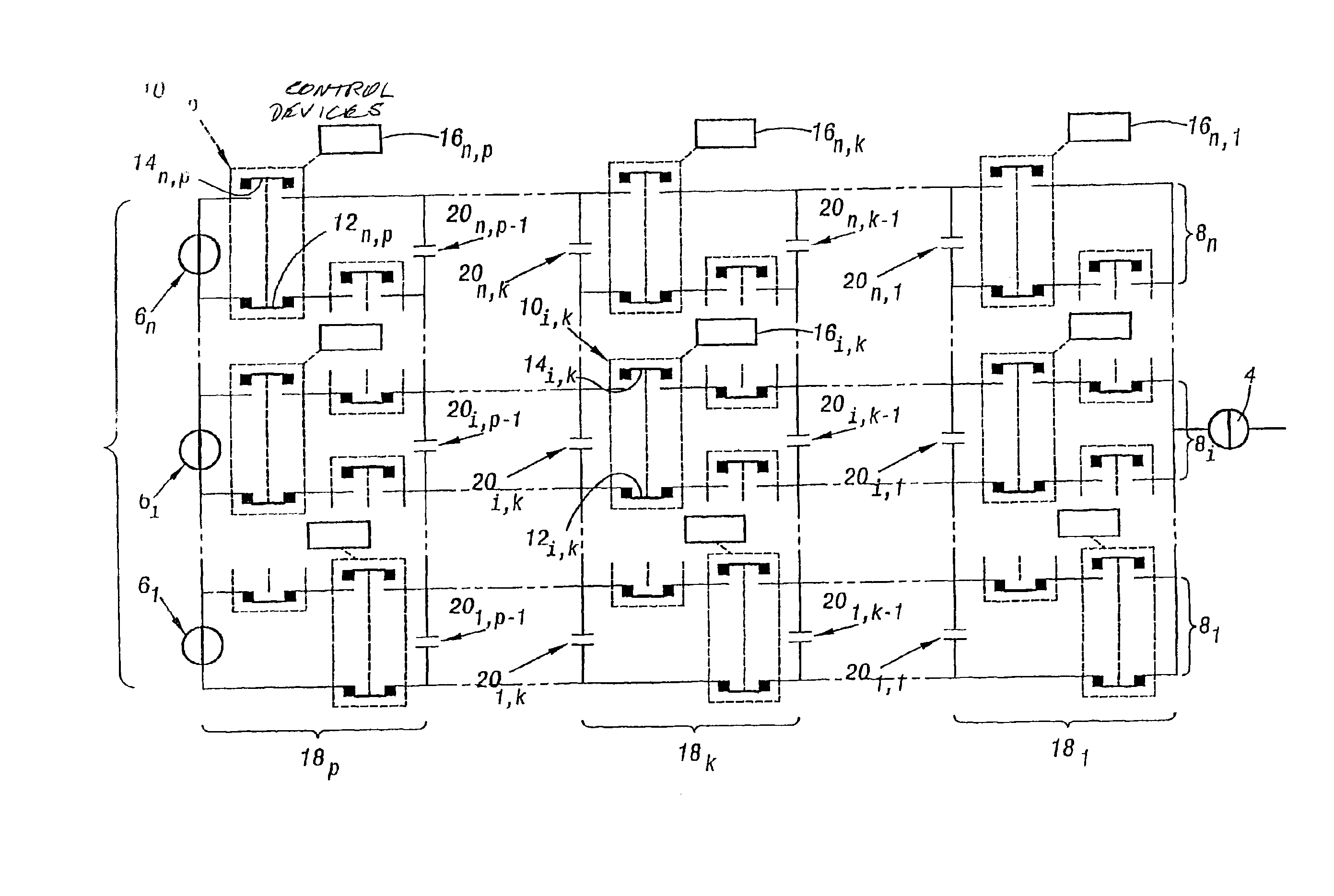
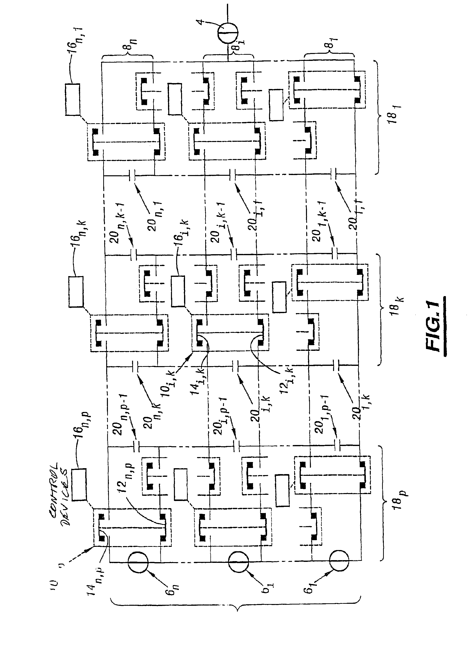
[0037]The device for reversible conversion of electrical energy which is shown in FIG. 1 has a DC voltage source 2 ensuring a potential difference of value E between its terminals and a current source 4 delivering a direct or alternating current I according to the application envisaged.

[0038]Thus, for example, when the current source delivers a symmetrical alternating current the conversion device corresponds to a voltage inverter or, taking account of the reversibility, to a current rectifier. The following description always assumes this particular case.

[0039]The voltage source consists of n secondary voltage sources 61, . . . , 6n connected in series and each defining between its terminals n successive stages 81, . . . , 8n. Any secondary source 6i is for example constituted by a capacitor and maintains a partial voltage En

between its terminals. In the following, the stages are numbered in the increasing order of the potential levels to which they are connected on the voltage sou...


PUM


Abstract

A device converting electric power between a voltage source and a current source, comprising several stages (8i) of switching cells (10i,k) comprising each two switches (12i,k, 14i,k), capacitors (20i,k) associated with the cells (10i,k) arranged in a row (18k) increasing from current source (4), control devices (16i,k) each connected to a cell (10i,k) and elements for monitoring the control devices (16i,k) . The stages (8i) define two end groups and at least an intermediate group of switches, the two end groups comprising switches of each cell belonging respectively to the first and last stage connected in series, the intermediate group comprising pairs of switches (12i,k, 14i−1,k) of cells belonging to two neighbouring stages connected in series. Furthermore, the capacitors (20i,k, 20n,k) of a common row (18k) are transversely connected in series between the two end groups.

Description

FIELD OF THE INVENTION[0001]The present invention relates to a device for reversible conversion of electrical energy between a DC voltage source and a current source.BACKGROUND OF THE INVENTION[0002]More particularly, the invention relates to such a device comprising, on the one hand, switching cells each having two switches, each switch itself being constituted by at least one component forming a switch, and, on the other hand, capacitors associated with the switching cells and adapted to maintain between the homologous terminals of the two switches of each cell a load voltage equal to a fraction of the voltage of the voltage source, increasing as a function of its rank starting from the current source, and the homologous terminals of the switches situated at the end of the device close to the current source being “short-circuitable”, and furthermore control devices each connected to a switching cell and adapted to control the switchings of the two switches of the cell whilst ensur...

Claims


Application Information

Patent Timeline
Patent Type & Authority Patents(United States)
IPC IPC(8): H02M7/48H02M7/797H02M7/483
CPCH02M7/483H02M2007/4835H02M7/487H02M1/007H02M1/0095H02M7/4837
Inventor GATEAU, GUILLAUMEMEYNARD, THIERRY ANTOINEFOCH, HENRI SIMON JACQUES
Owner INST NAT POLYTECHN DE TOULOUSE 50 PART INTEREST
Why Eureka
Try Eureka