Method of programming and erasing multi-level flash memory

Active Publication Date: 2005-10-25
MACRONIX INT CO LTD
View PDF12 Cites 45 Cited by
  • Summary
  • Abstract
  • Description
  • Claims
  • Application Information

AI Technical Summary

Benefits of technology

[0014]In summary, the present invention increases the potential of the programming voltage of the multi-level flash memory and decreases the potential of the erasing electron of the multi-level flash memory by adding one additional programming vo

Problems solved by technology

During programming of the multi-flash memory, if the sense margin in each tracking of the reading current is not high enough misjudgments of the multi-flash memory will eas

Method used


Image

  • Method of programming and erasing multi-level flash memory
  • Method of programming and erasing multi-level flash memory
  • Method of programming and erasing multi-level flash memory

Examples


Embodiment Construction

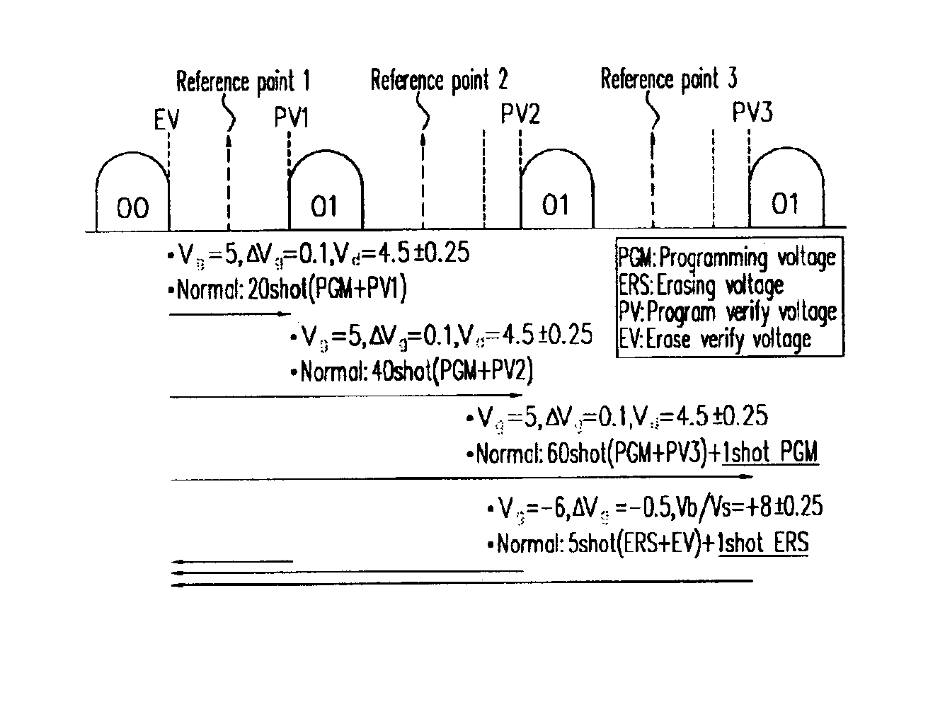
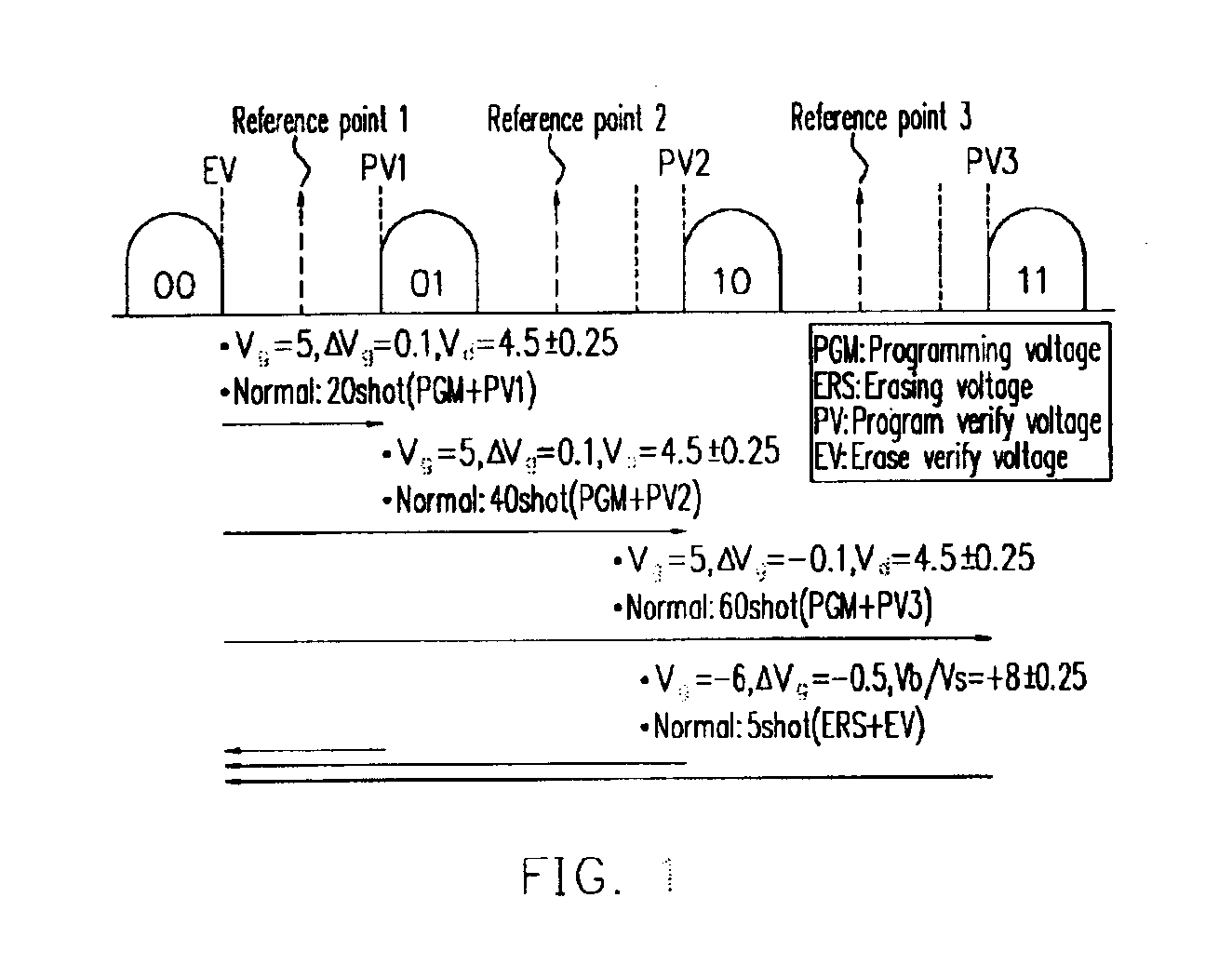
[0022]The present invention applies the gate voltage to the gate of the flash memory and applies the drain voltage to the drain of the flash memory. The source is grounded, and the voltage value of the gate voltage shot into the gate is increased upward stepwise, so that the hot electrons in the flash memory channel are injected and stay in the floating gate of the flash memory via the channel. The electrons in the floating gate are provided with different electron distribution due to different gate voltage shot times to represent flash memory having different states. When the method is applied to a full program of the flash memory, an additional program verify voltage is shot into the gate of the flash memory. That is, if 20 voltage shots are needed for the flash memory to program the state value of 01, 20 programming voltages and one additional gate voltage is shot. When multi-flash memory of the present invention erases the flash memory, the gate voltage is applied to the gate of...


PUM


Abstract

A programming method of the multi-level flash memory comprises shooting a programming voltage that is increasing upwards stepwise each time into the gate of the multi-level flash memory, and following, shooting a program verify voltage that is decreasing downwards to program a multi-level in the multi-level flash memory and shooting an additional programming voltage into the multi-level flash memory after the last program verify voltage is shot. An erasing method of the multi-level flash memory comprises shooting an erasing voltage that is decreasing downwards stepwise each time into a gate of the multi-level flash memory, and following, shooting a erase verify voltage that is increasing upwards to erase a multi-level in the multi-level flash memory and shooting an additional voltage into the multi-level flash memory after the last erase verify voltage is shot.

Description

CROSS REFERENCE TO RELATED APPLICATIONS[0001]This application claims the priority benefit of Taiwan application serial no. 91100639, filed Jan. 17, 2002.BACKGROUND OF INVENTION[0002]1. Field of Invention[0003]The present invention generally relates to a programming and erasing method of flash memory, and more particularly, to a programming and erasing method of multi-level flash memory.[0004]2. Description of Related Art[0005]In the process of programming and erasing a flash memory bit, in order to have the flash memory describe the binary state and the trinity state, or . . . state, (00, 01, 10, 11 state or 000, 001, 010, 011, 100, 101, 110, 111 state, or . . . state), the means of changing the gate voltage of the flash memory periodically is commonly used to limit the number of the gate voltage shooting times, so that the channel of the flash memory is able to generate the channel hot electrons, and the state when the channel hot electrons are injected to the floating gate via the...

Claims


Application Information

Patent Timeline
IPC IPC(8): G11C11/56
CPCG11C11/5628G11C11/5635G11C16/12G11C2211/5621
Inventor FAN, TSO-HUNGYEH, CHIH-CHIEHLU, TAO-CHENG
Owner MACRONIX INT CO LTD
Why Eureka
Try Eureka