
Traffic manager for network switch port

a traffic manager and network switch technology, applied in data switching networks, store-and-forward switching systems, time-division multiplexing selection, etc., can solve the problem of reducing the throughput rate of the output port forwarding packets over a given bus or bus channel, the rate of the flow queue and output resource is not independently adjustable, and the rate of the output port forwarding packets is often subject to contractual limits

Active Publication Date: 2005-10-25
ZETTACOM +1
View PDF4 Cites 118 Cited by
  • Summary
  • Abstract
  • Description
  • Claims
  • Application Information

AI Technical Summary

Benefits of technology

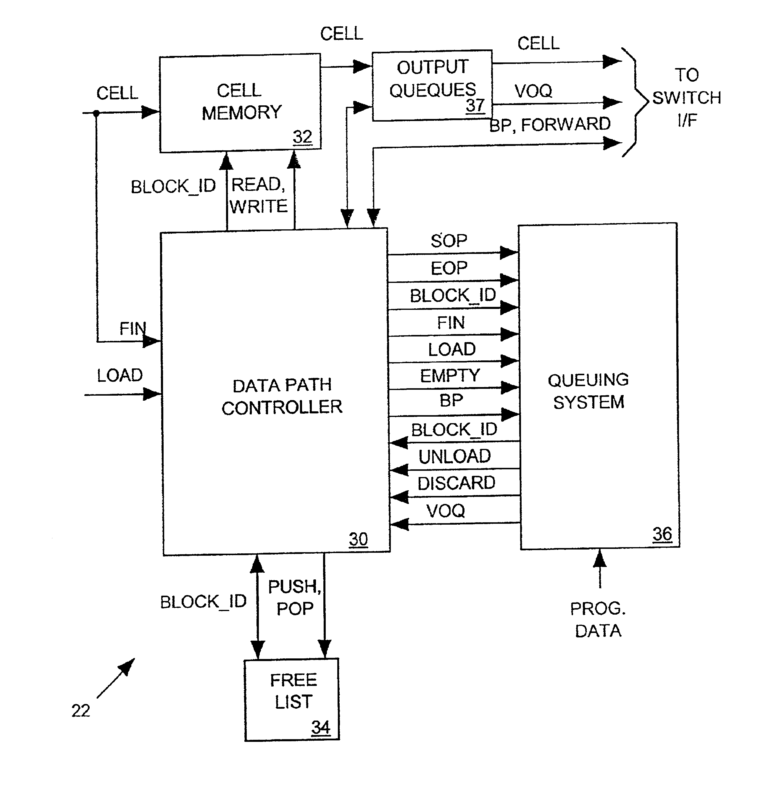
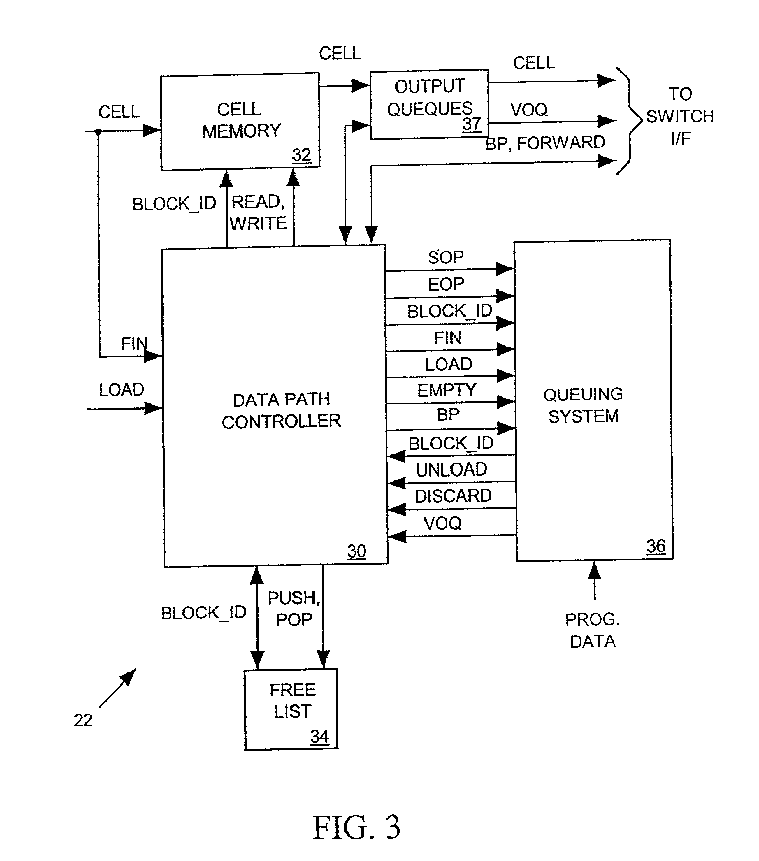
[0020]It is accordingly an object of the invention to provide a traffic manager that can independently adjust rates at which it a network switch input or output port forwards cells of each flow queue and the rate at which each forwarding resource receives cells from the input or output port.

Problems solved by technology

The rate at which an output port forwards packets over a given bus or bus channel is often subject to contractual limits.
Secondly, a traffic manager may have to control the rate at which it forwards packets outward on a particular bus, or each bus channel, irrespective of the flows to which those packets are assigned.
One difficulty with the prior art rate shaping system of FIG. 11 is that the flow queue and output resources rates are not independently adjustable.
However in a network switch input port, it may not be necessary or desirable to shape an output resource's rate.
The need to shape the output resource forwarding rates in a network switch input port can lead to an undesirable reduction in throughput.

Method used


Image

  • Traffic manager for network switch port
  • Traffic manager for network switch port
  • Traffic manager for network switch port

Examples


Embodiment Construction

Network Switch

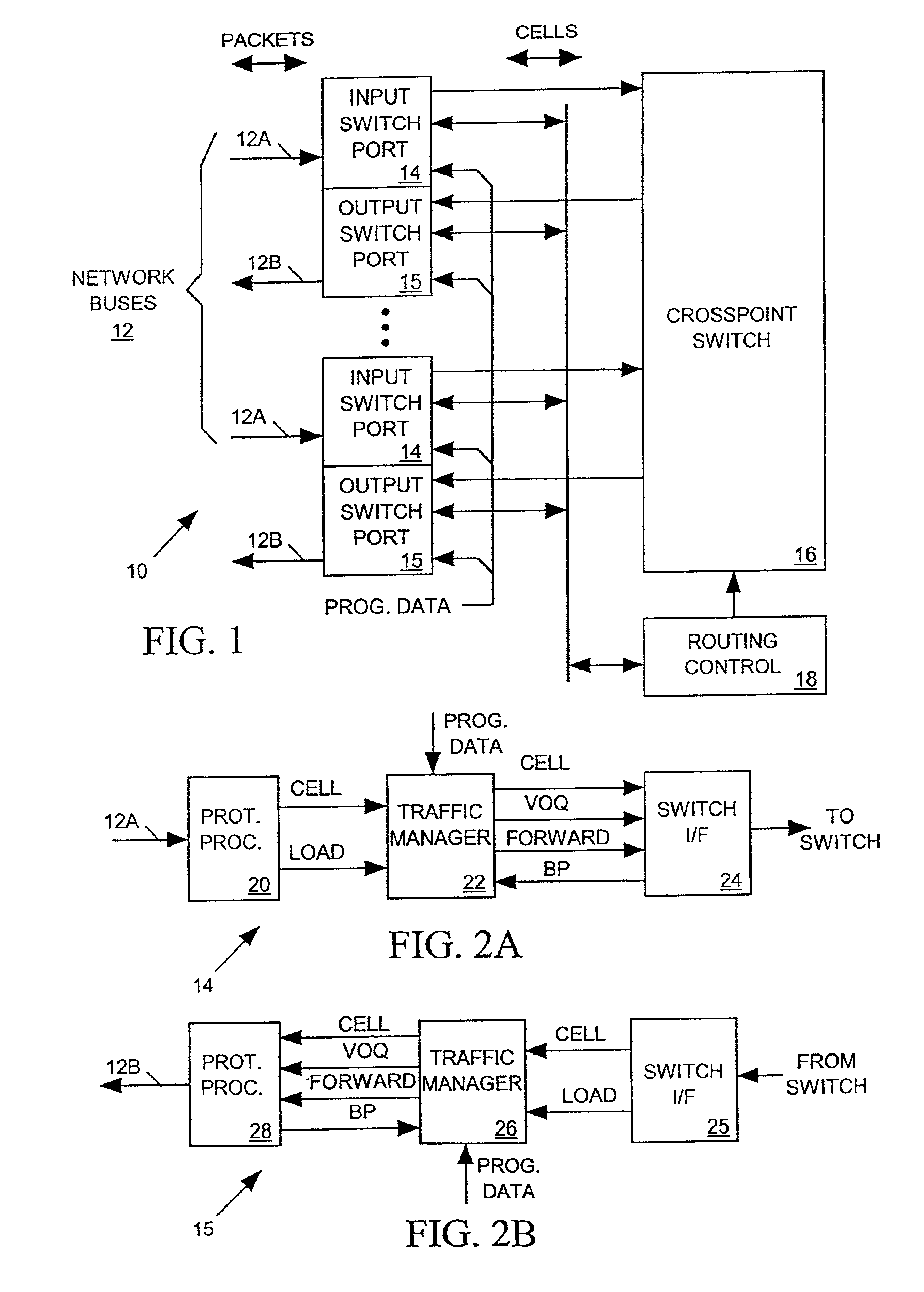
[0034]FIG. 1 illustrates a network switch 10 in accordance with the invention for routing network transmissions (packets) between a set of network buses 12. Network switch 10 includes input switch ports 14, output switch ports 15, a crosspoint switch 16, and a routing control circuit 18. Each input switch port 14 receives incoming packets arriving on a separate input bus 12A and each output port 15 forwards outgoing packets on a separate output bus 12B. Although not shown in FIG. 1, each input switch port 14 may receive packets on more than one incoming bus 12A and each output port may selectively forward outgoing packets on more than one outgoing bus 12B or output bus channel. Crosspoint switch 16 selectively provides signal paths between input switch ports 14 and output ports 15 in response to control data from routing control circuit 18 based on routing requests from input switch ports 14.

[0035]Incoming packets arriving on buses 12A are network data transmissions th...


PUM


Abstract

A traffic manager for a network switch input or output port stores incoming cells in a cell memory and later sends each cell out of its cell memory toward one of a set of forwarding resources such as, for example, another switch port or an output bus. Data in each cell references the particular forwarding resource to receive the cell. Each cell is assigned to one of several flow queues such that all cells assigned to the same flow queue are to be sent to the same forwarding resource. The traffic manager maintains a separate virtual output queue (VOQ) associated with each forwarding resource and periodically loads a flow queue (FQ) number identifying each flow queue into the VOQ associated with the forwarding resource that is to receive the cells assigned to that FQ. The traffic manager also periodically shifts an FQ ID out of each non-empty VOQ and forwards the longest-stored cell assigned to that FQ from the cell memory toward its intended forwarding resource. The traffic manager separately determines the rates at which it loads FQ IDs into VOQs and the rates at which it shifts FQ IDs out of each non-empty VOQ. Thus the traffic manager is able to separately control the rate at which cells of each flow queue are forwarded and the rate at which each forwarding resource receives cells.

Description

CROSS-REFERENCE TO RELATED APPLICATION[0001]This application is filed as a continuation-in-part of U.S. patent application Ser. No. 09 / 847,078 filed May 1, 200 now U.S. Pat. No. 6,687,781.BACKGROUND OF THE INVENTION[0002]1. Field of the Invention[0003]The present invention relates in general to a network switch for routing traffic between network buses, and in particular to a traffic manager for controlling rates at which an input or output port of the network switch forwards traffic into or away from the network switch.[0004]2. Description of Related Art[0005]A network switch routes data transmissions such as ethernet packets between a set of network buses. A typical network switch includes a set of input ports for receiving network traffic arriving on input buses, a set of output ports for forwarding traffic outward on output buses, and a switch fabric such as a crosspoint switch for routing traffic between the input and output ports.[0006]Network traffic often travels over buses ...

Claims


Application Information

Patent Timeline
Patent Type & Authority Patents(United States)
IPC IPC(8): H04Q11/04H04L12/56
CPCH04L49/255H04L49/3081H04Q11/0478H04L2012/5631H04L2012/5679H04L2012/5681
Inventor WYNNE, JOHN M.DOOLEY, DAVID L.DIVIVIER, ROBERT J.
Owner ZETTACOM
Learn More