Pivotal knife mounting arrangement

a mounting arrangement and knife technology, applied in the field of pivotal mounting arrangements, can solve the problems of insufficient hex configuration of the outer surface of the wrench, deformation of the hex configuration of the wrench, and inability to remove the wrench adequately, so as to achieve the effect of improving the mounting arrangement and positive retention

Inactive Publication Date: 2005-11-01
VERMEER MFG CO
View PDF18 Cites 10 Cited by
  • Summary
  • Abstract
  • Description
  • Claims
  • Application Information

AI Technical Summary

Benefits of technology

[0010]According to the present invention there is provided an improved mounting arrangement for a knife to a disc for use on a rotary disc cutter that eliminates the need for a threaded connector and the associated nut, providing a positive retention method on the top side of the disc. In addition it provides a method of removing the knife from the disc without the use of wrenches, simply requiring a tool to pry, such as a screw driver. A further feature is a low profile retainer that does not need to be protected by a wear protector.

Problems solved by technology

This results in inherent dulling and wear.
If nut 16 is subjected to sufficient wear, the hex configuration of its outer surface can be degraded to the point that a wrench no longer mates adequately to allow removal.
This mounting arrangement requires that the several pieces be disassembled with wrenches in order to maintain the knives which is costly and difficult due to the number of knives on a machine.

Method used


Image

  • Pivotal knife mounting arrangement
  • Pivotal knife mounting arrangement
  • Pivotal knife mounting arrangement

Examples


Embodiment Construction

[0037]Referring now to the drawings, like reference numerals designate identical or corresponding parts throughout the several views. The included drawings reflect the current preferred and alternate embodiments. There are many additional embodiments that may utilize the present invention. The drawings are not meant to include all such possible embodiments.

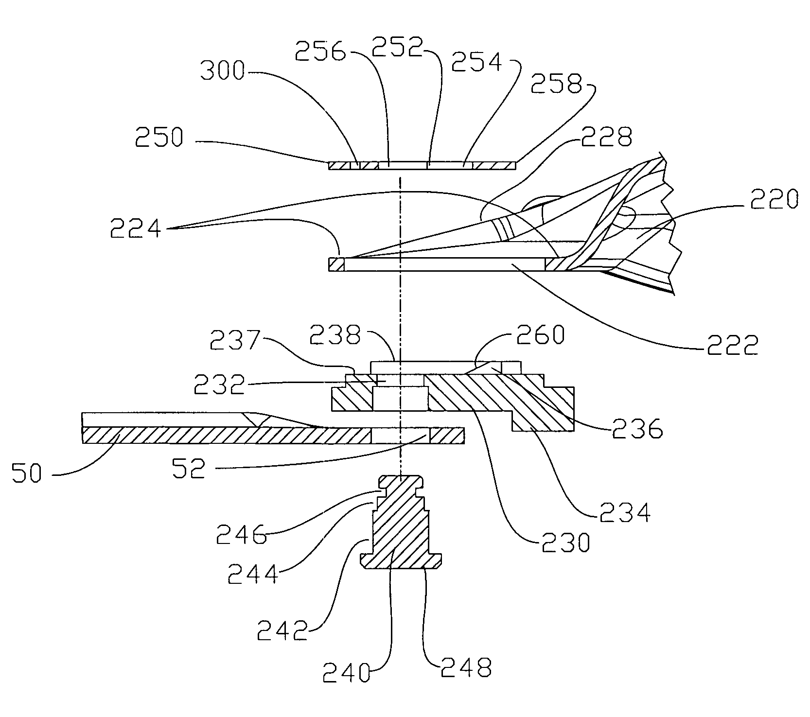
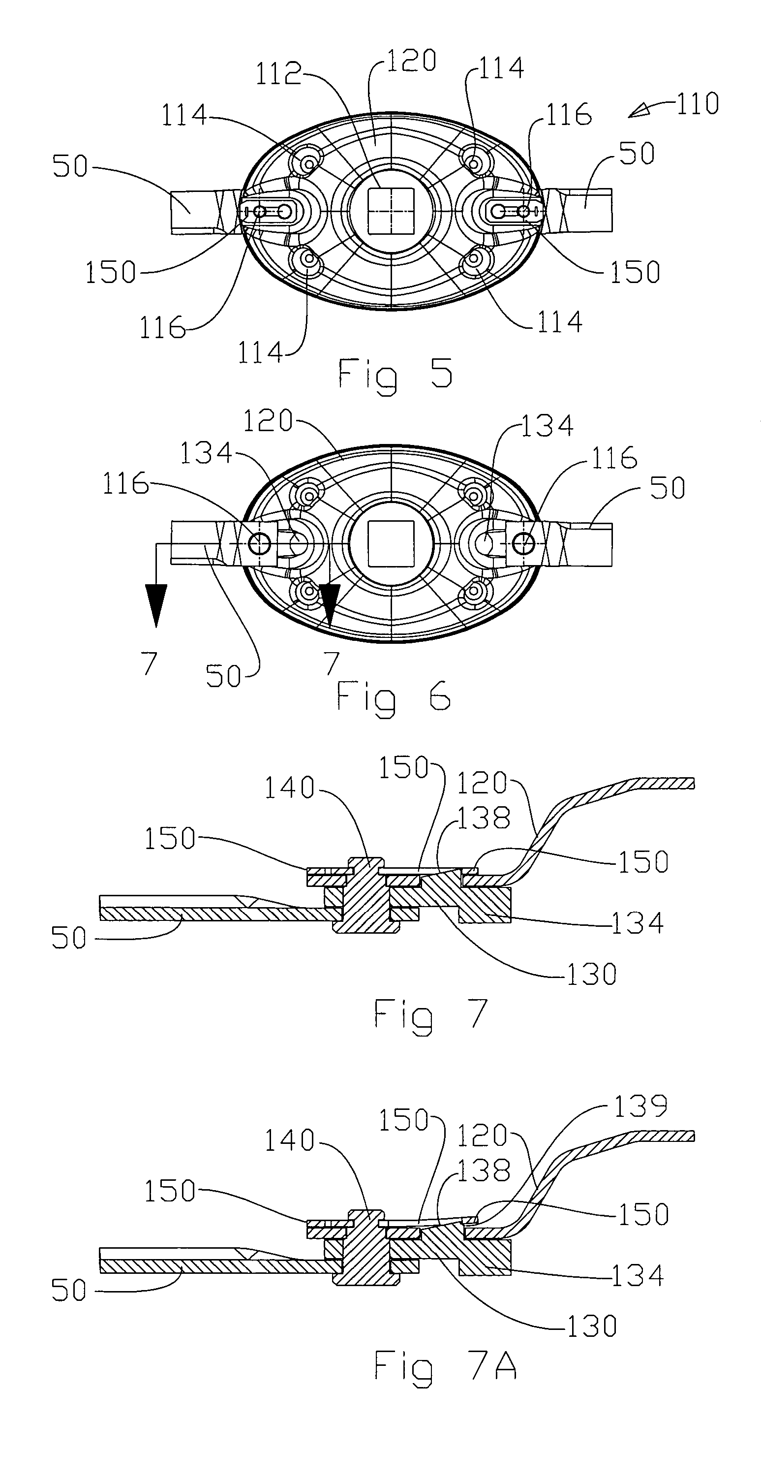
[0038]The FIGS. 5–7 illustrate a mower disc assembly 110 of the present invention. A disc 120 includes a center pilot hole 112 that controls its alignment and location when installed onto a cutter bar which is comprised of a series of gears, a supporting frame / housing, and driveline to transfer power from a tractor PTO to the cutterbar. Additional holes 114 allow retainers, not shown, to securely attach other components such as crop deflectors, not shown, to the mower disc. Two knives 50 are installed onto the bottom of disc body 120, each with a knife adapter 130, a pin 140 and a retainer 150. The knife is free to rotate about pi...


PUM

PropertyMeasurementUnit
speedsaaaaaaaaaa
transition areaaaaaaaaaaa
outer diameteraaaaaaaaaa

Abstract

An improved mounting arrangement for a knife to a disc for use on a rotary disc cutter that eliminates the need for a threaded connector and the associated nut is disclosed. It also provides a positive retention method on the top side of the disc. In addition, it provides a method of removing the knife from the disc without the use of wrenches, simply requiring a tool for prying, such as a screw driver. A further feature is a low profile retainer that does not need to be protected by a wear protector.

Description

CROSS-REFERENCE TO RELATED APPLICATIONS[0001]This application is a Divisional of U.S. patent application Ser. No. 10 / 387,100, filed Mar. 12, 2003, now U.S. Pat. No. 6,834,486 entitled PIVOTAL KNIFE MOUNTING ARRANGEMENT.STATEMENT-REGARDING FEDERALLY SPONSORED RESEARCH OR DEVELOPMENT[0002]Not ApplicableFIELD OF THE INVENTION[0003]The present invention relates to a pivotal mounting arrangement for mounting a knife to a rotary disc, which makes replacement, or reorientation of the blade possible using only common tools.BACKGROUND OF THE INVENTION[0004]Knives used on rotary disc mowers contact the crop material at high speeds, in order to cut effectively. This results in inherent dulling and wear. At times these knives contact other objects such as the ground, rocks etc. causing additional wear. As a result the knives must routinely be maintained.[0005]The knives are pivotally mounted to discs, in a manner to reduce impact loading on the sharpened edge when striking an obstacle. FIGS. 1–...

Claims


Application Information

Patent Timeline
Patent Type & Authority Patents(United States)
IPC IPC(8): A01D34/73
CPCA01D34/733Y10T29/49721Y10S56/20A01D34/736
Inventor THOMPSON, KENTBENTZINGER, RUSTIN V.
Owner VERMEER MFG CO
Why Eureka
Try Eureka