

Rolling mill and method for operating same
a technology of rolling mill and rolling mill, which is applied in the direction of rare end control device, roll mill control device, manufacturing tools, etc., can solve the problems of low horizontal dynamic stiffness of rolling mill, affecting high-efficiency rolling,
- Summary
- Abstract
- Description
- Claims
- Application Information
AI Technical Summary
Benefits of technology
Problems solved by technology
Method used
Image

Examples
first embodiment
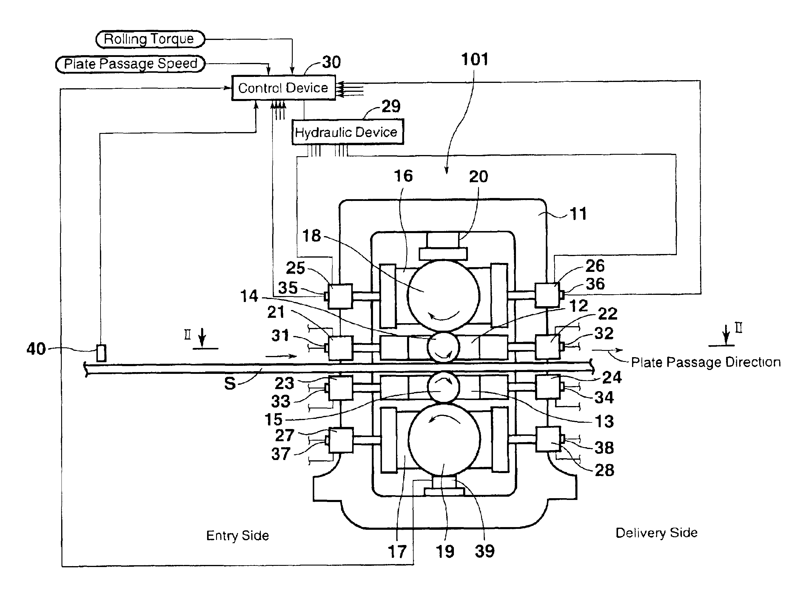
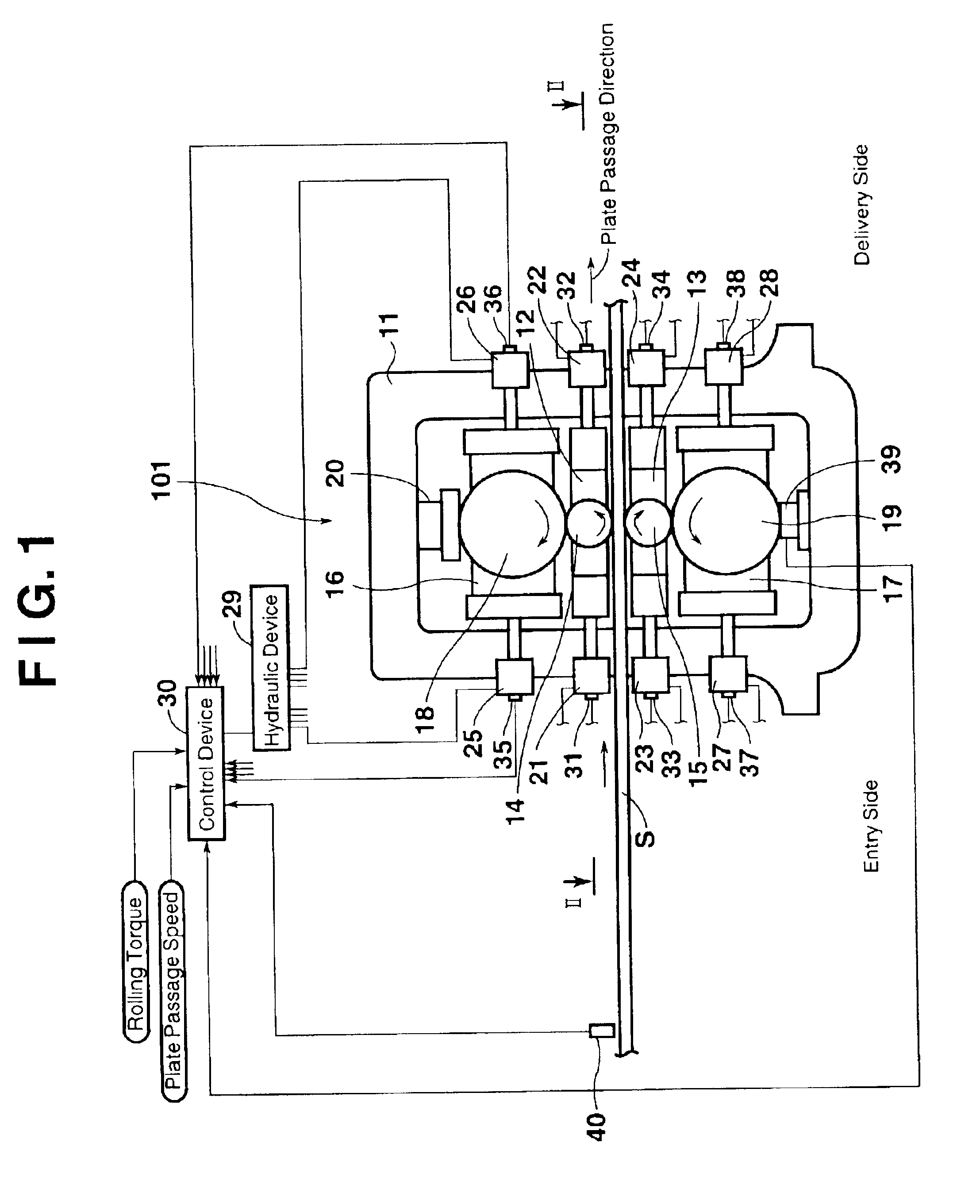
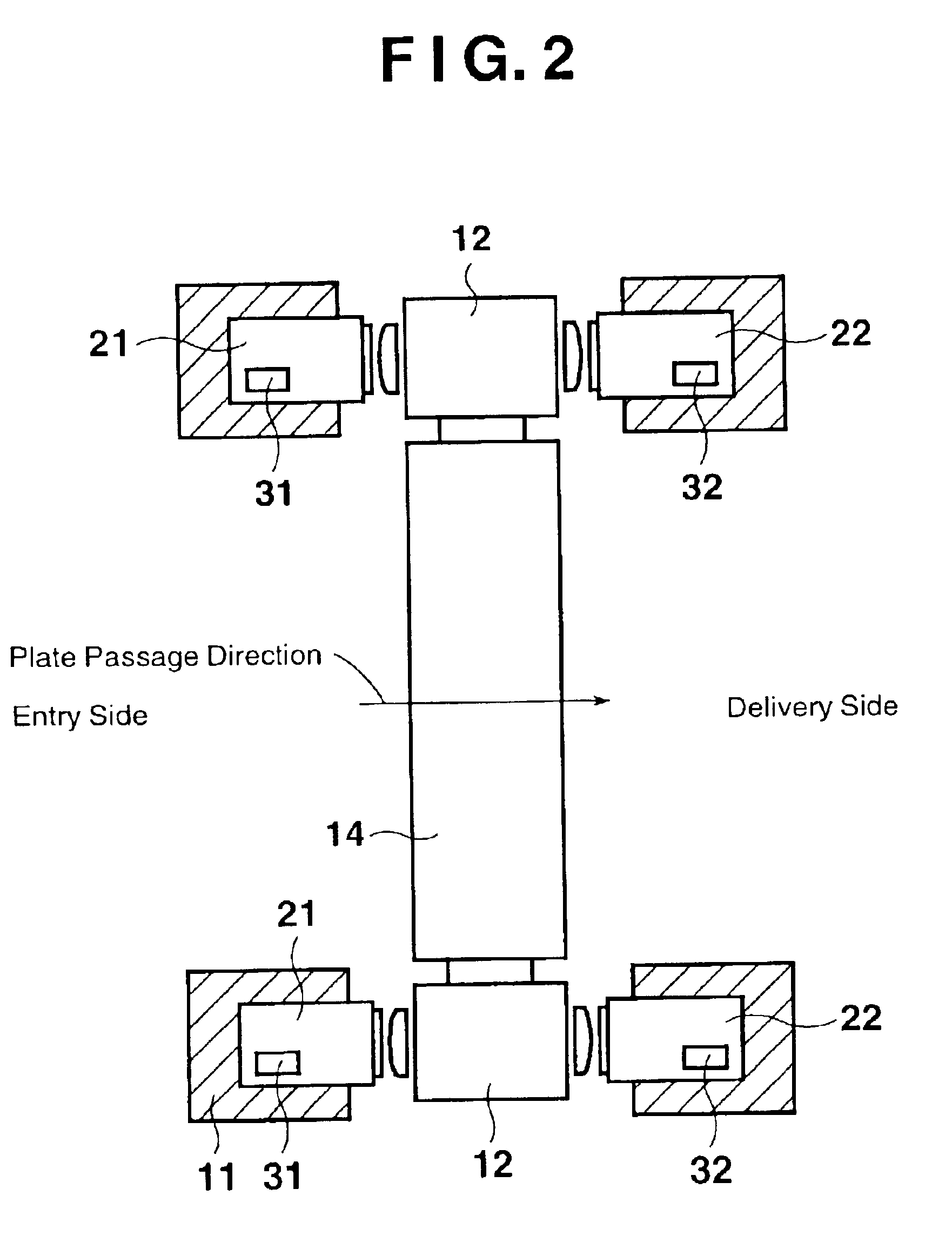
[0030]In a rolling mill 101 according to the first embodiment, as shown in FIGS. 1 and 2, upper and lower work roll chocks 12 and 13 as a pair are supported in a housing 11. Shaft portions of upper and lower work rolls 14 and 15 as a pair are rotatably supported by the upper and lower work roll chocks 12 and 13, respectively, and the upper work roll 14 and the lower work roll 15 are opposed to each other. Upper and lower backup roll chocks 16 and 17 as a pair are supported above and below the upper and lower work roll chocks 12 and 13. Shaft portions of upper and lower backup rolls 18 and 19 as a pair are rotatably supported by the upper and lower backup roll chocks 16 and 17, respectively. The upper backup roll 18 and the upper work roll 14 are opposed to each other, while the lower backup roll 19 and the lower work roll 15 are opposed to each other. A screw down device 20 for imposing a rolling load on the upper work roll 14 via the upper backup roll 18 is provided in an upper por...
second embodiment
[0048]In a method for operating the rolling mill according to the second embodiment, the control device 30 controls the hydraulic device 29 such that before the rear end portion of the rollable material S passes between the work rolls 14 and 15, the pressing force on the roll chocks 12, 13, 16, 17 by the hydraulic cylinders 21 to 28 is set to be high, and after the rollable material S passes between the work rolls 14 and 15, this pressing force is set to be low.
[0049]That is, as shown in FIGS. 3 and 5, the rolling of the rollable material S by the rolling mill 101 nears completion, and the end portion detection sensor 40 detects the rear end portion of the rollable material S. In this case, the control device 30 controls the hydraulic device 29 at a time t6, a predetermined time after detection by the end portion detection sensor 40, thereby raising the working oil pressure of the hydraulic cylinders 21 to 28. At a time t7, the working oil pressure of the hydraulic cylinders 21 to 2...
third embodiment
[0052]In a method for operating the rolling mill according to the third embodiment, the control device 30 controls the hydraulic device 29 such that before the rear end portion of the rollable material S passes between the work rolls 14 and 15, the pressing force on the roll chocks 12, 13, 16, 17 by the hydraulic cylinders 21 to 28 is set to be high, and after this rollable material S passes between the work rolls 14 and 15 and a front end portion of a succeeding rollable material S is completely engaged between the work rolls 14 and 15, this pressing force is set to be low.
[0053]That is, as shown in FIGS. 3 and 6, the rolling of the rollable material S by the rolling mill 101 nears completion, and the end portion detection sensor 40 detects the rear end portion of the rollable material S. In this case, the control device 30 controls the hydraulic device 29 at a time t6, thereby raising the working oil pressure of the hydraulic cylinders 21 to 28. At a time t7, the working oil press...
PUM
| Property | Measurement | Unit |
|---|---|---|
| Force | aaaaa | aaaaa |
Abstract
Description
Claims
Application Information