Valve

a valve and elastic member technology, applied in the field of valves, can solve the problems of short durability, low withstanding pressure of valves made only from elastic members, and damage to sealing, and achieve the effect of less nois

Inactive Publication Date: 2005-11-01
MIURA COMPANY LIMITED
View PDF13 Cites 29 Cited by
  • Summary
  • Abstract
  • Description
  • Claims
  • Application Information

AI Technical Summary

Benefits of technology

[0008]It is an object of the present invention to provide a valve enabling complete prevention of leakage and a backflow and having durability and less noise. It is further object o...

Problems solved by technology

The valve made only from the elastic member is low in withstanding pressure and short of durability.
In the case of using only the metal seal, there is a problem that a small dust being interposed between the valve sheet and the valve element made from an inelastic member, which is so-called dust clogging, easily damages sealing, and tends to cause leakage and a backflow.
Also, if the dust clogging occurs in the valve with metal seal structure, the dust may be washed away by the next flow of fluid, which eliminates reproducibility of leakage or th...

Method used


Image

  • Valve
  • Valve
  • Valve

Examples


working example

[0041

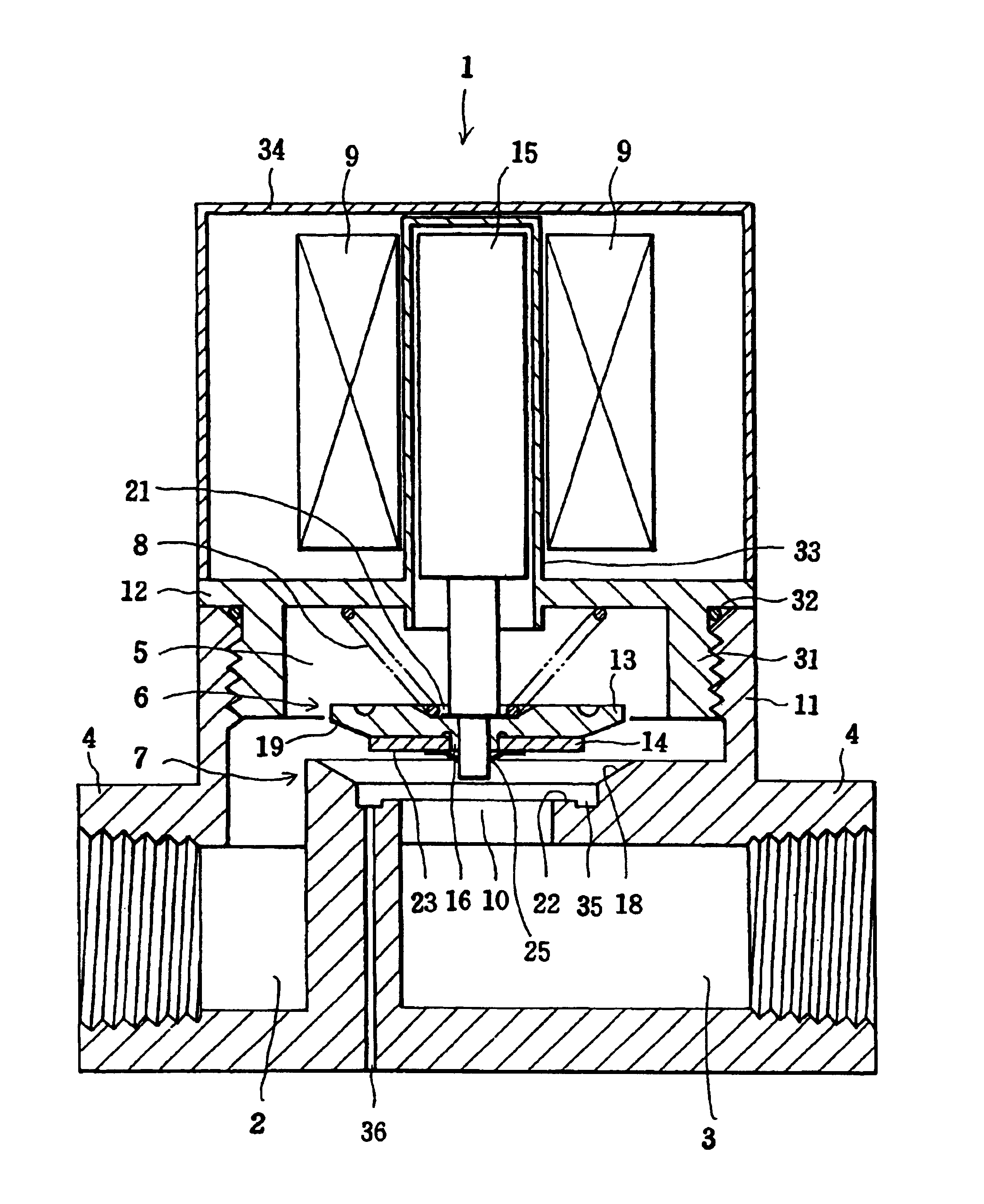
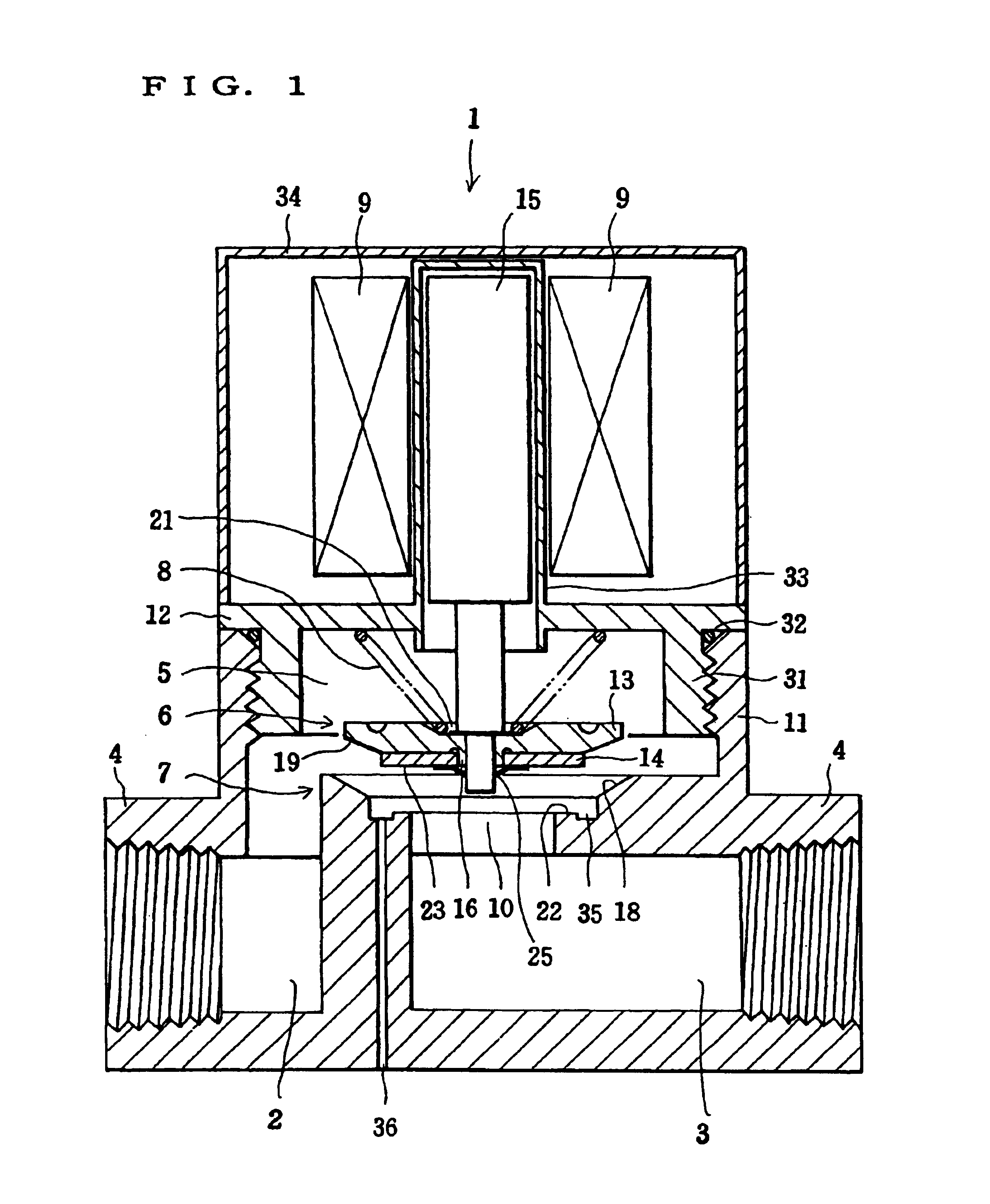
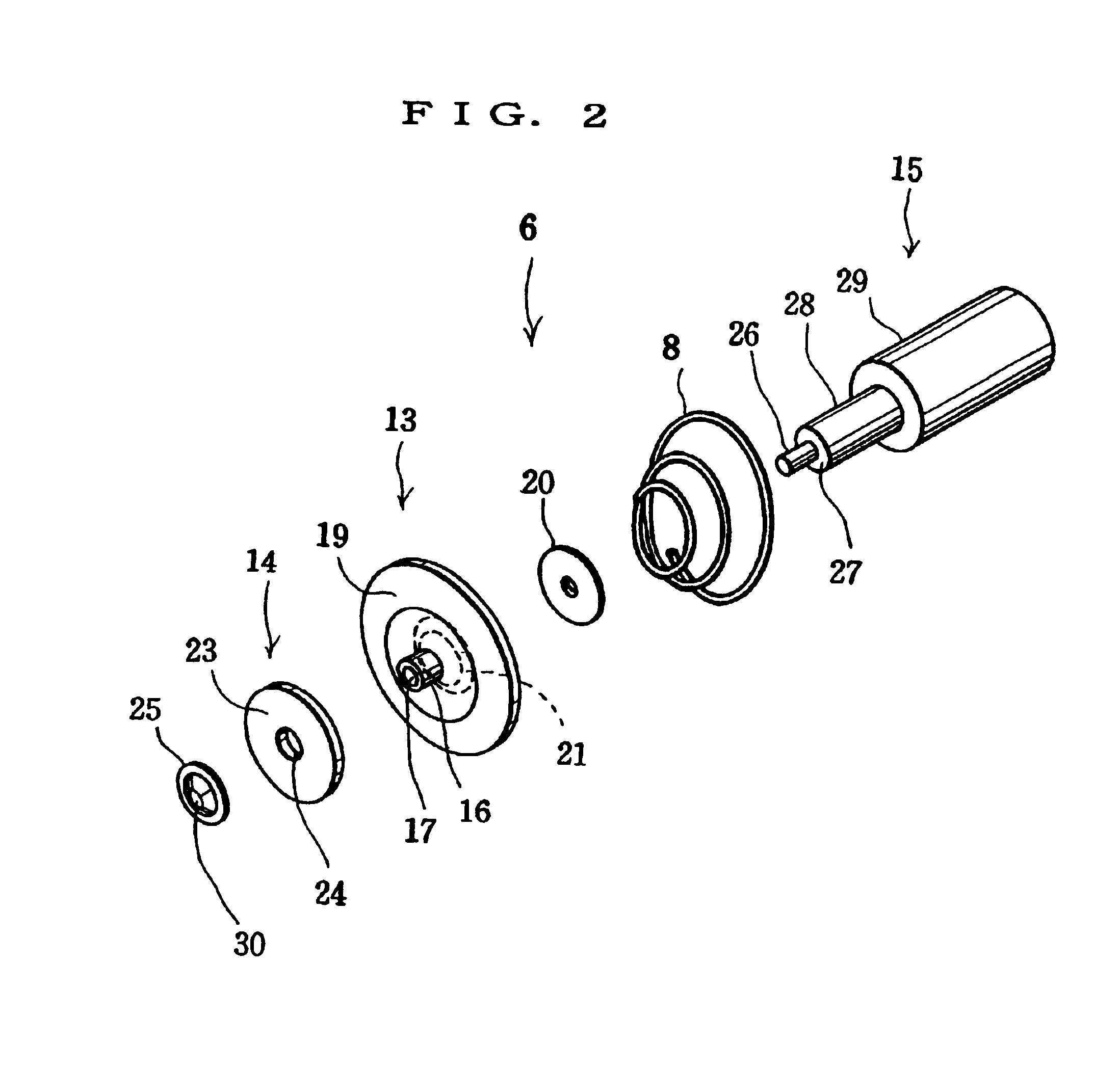
[0042]Hereinbelow, specific working examples of the present invention will be described in detail with reference to accompanying drawings. A preferred first working example is described in the state of being applied to a solenoid valve, which is a valve for intercepting a fluid line. FIG. 1 is a schematic cross sectional view showing the structure of a solenoid valve in the state of opening a fluid line.

[0043]In FIG. 1, a solenoid valve 1 has a valve chamber 5 in a valve main body 4 equipped with a cylindrical fluid inlet 2 and a cylindrical fluid outlet 3. In the valve chamber 5, a valve element 6 is movably disposed, and a valve seat 7 that comes into contact with the valve element 6 is provided. Further, the solenoid valve 1 is composed of a compression spring 8 for bringing the valve element 6 into contact with the valve seat 7, and an electromagnetic coil 9 for pulling the valve element 6 away from the valve seat 7 against the pressing force of the compression spring 8.

[00...


PUM


Abstract

There is provided a valve enabling complete prevention of leakage and a backflow and having durability and less noise, and further there may be implemented a valve capable of predicting the tendency of occurrence of damage on the functions of the valve before the functions of the valve are actually damaged. In a valve having a valve chamber 5 formed between a fluid inlet 2 and a fluid outlet 3, a valve element 6 disposed in the valve chamber 5 is composed of an elastic member and an inelastic member.

Description

BACKGROUND OF THE INVENTION[0001]The present invention relates to a valve for intercepting a line of fluid.[0002]In an apparatus using fluid, the flow of the fluid is normally controlled by using various kinds of valves. For intercepting lines of fluid, a solenoid valve is often used as a valve for controlling opening and closing of the fluid lines, while as a valve for intercepting a backflow of fluid, a check valve is provided in most cases. These valves are each selected depending on equipment for use or conditions of pipes.[0003]For example, in the pipes for fuel system such as boilers, there is provided a valve for controlling supply of fuel. Since boiler fuel is a light fuel or a gas fuel in nature, it is necessary to take all possible measures against leakage of the boiler fuel to ensure safety. Accordingly, in order to prevent leakage of fuel, there have conventionally been made efforts including combining various types of valves and disposing a plurality of valves in series...

Claims


Application Information

Patent Timeline
IPC IPC(8): F16K25/00F16K31/06F16K15/06F16K1/32F16K1/36F16K15/02F16K1/34F16K37/00
CPCF16K1/36F16K15/063F16K25/00F16K31/0655F16K31/0693Y10T137/0402Y10T137/5762Y10T137/8326F16K31/06
Inventor KAYAHARA, TOSHIHIROWATANABE, SHIGEHIROTAKEDA, TOMOHISA
Owner MIURA COMPANY LIMITED
Why Eureka
Try Eureka