
Utility valve extension

a technology for extending the use valve, which is applied in the direction of valves, mechanical devices, engine components, etc., can solve the problems of limited access to the flow control valve, difficulty in bending down and contorting themselves to access such a valve, etc., and achieves the effect of durable and reliable construction, easy and efficient manufacturing

Inactive Publication Date: 2005-11-01
CORRAL FELIPE H
View PDF9 Cites 16 Cited by
  • Summary
  • Abstract
  • Description
  • Claims
  • Application Information

AI Technical Summary

Benefits of technology

[0018]It is another object of the invention to provide a control device for use in conjunction with utility control valves that may be easily and efficiently manufactured.
[0019]It is another object of the invention to provide a control device for use in conjunction with utility control valves that is durable and reliable in construction.

Problems solved by technology

In many of these situations, access to the on / off flow control valve is limited because of lack of space.
For persons with disabilities or old age, bending down and contorting themselves to access such a valve may be difficult or almost impossible.
None of these patents addresses the issue of providing a device that can be used by almost any person, regardless of age, height, or physical condition, for a wide variety of appliances found in a residence to easily shut off the flow of water or gas to the appliance.

Method used


Image

  • Utility valve extension
  • Utility valve extension
  • Utility valve extension

Examples


Embodiment Construction

[0040]In the following description of the present invention, reference is made to the accompanying drawings, which form a part thereof, and in which are shown, by way of illustration, exemplary embodiments illustrating the principles of the present invention and how it may be practiced. It is to be understood that other embodiments may be utilized to practice the present invention and structural and functional changes may be made thereto without departing from the scope of the present invention.

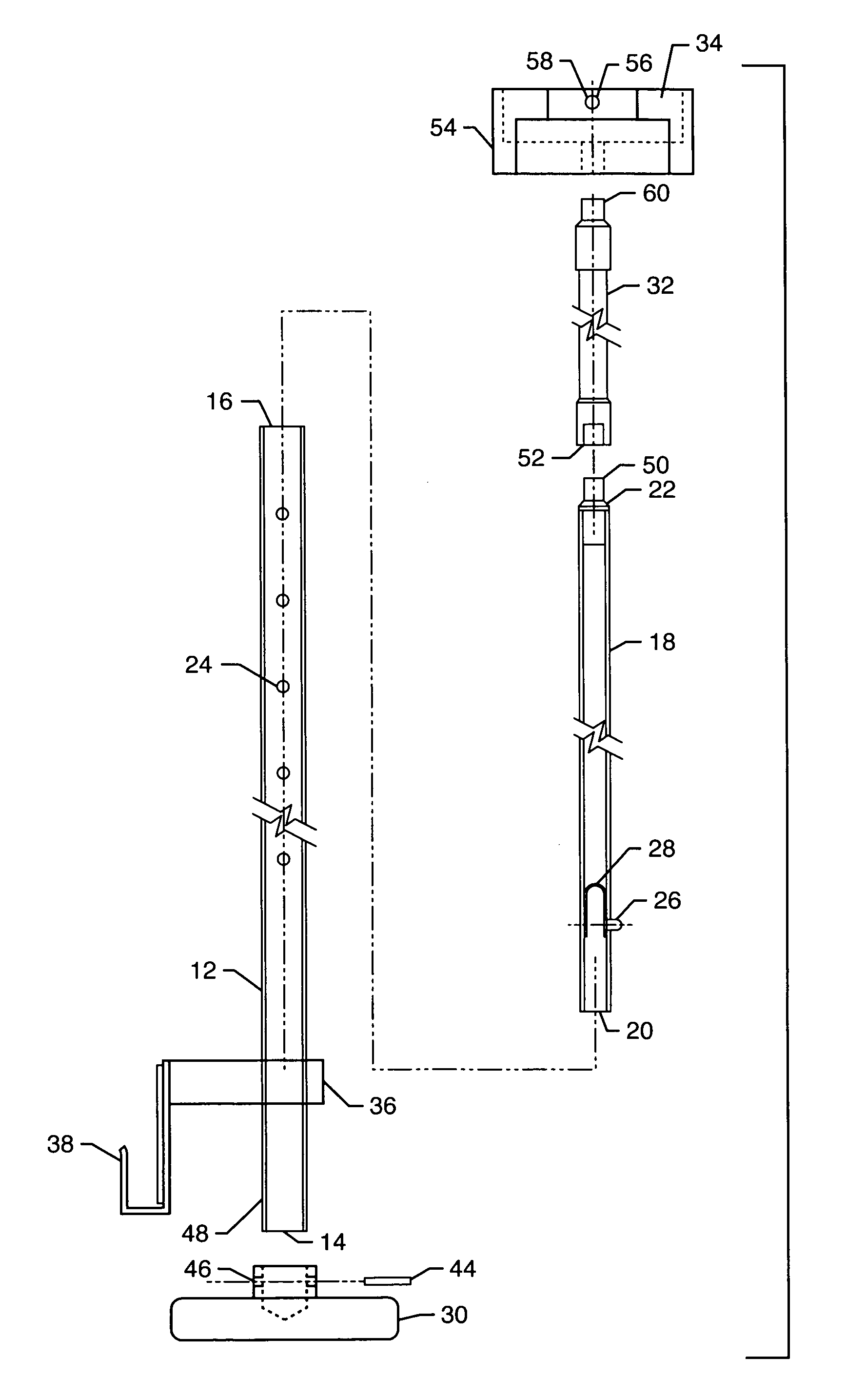
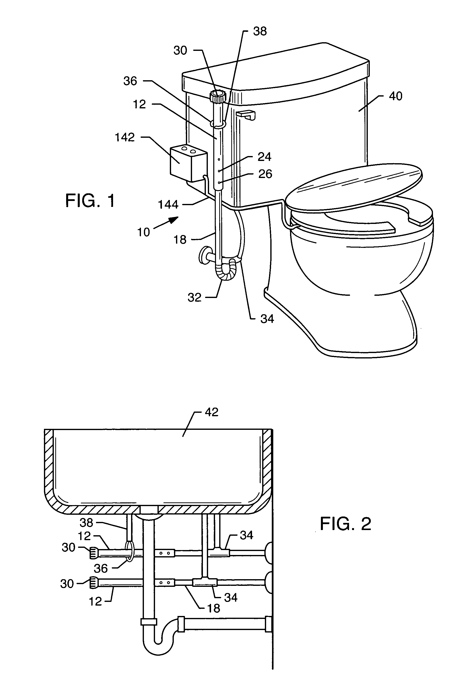
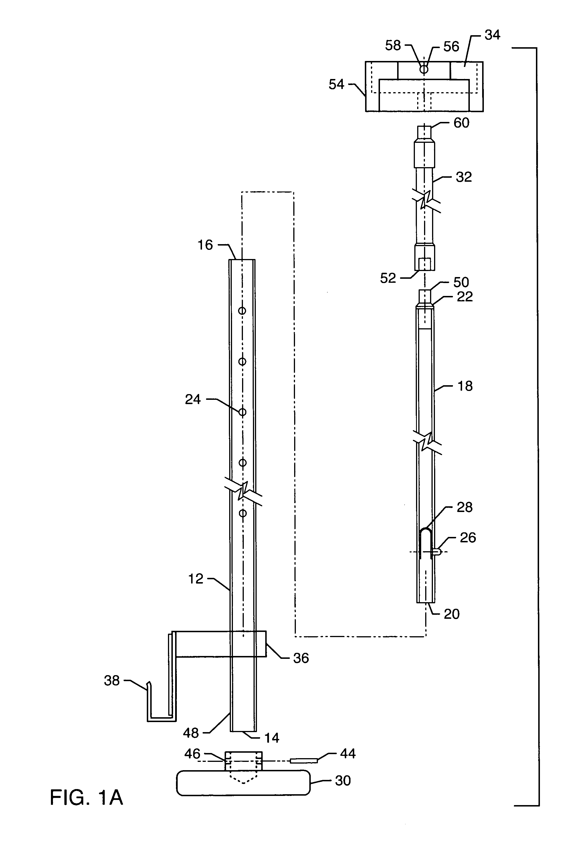
[0041]An extension device according to the present invention is generally referred to by the reference numeral 10. FIG. 1 illustrates a perspective view of extension 10 in use with a toilet 40. FIG. 1A shows an exploded view of extension 10. Extension 10 includes sleeve 12 having first end 14 and second end 16, and shaft 18 having first end 20 and second end 22. First end 20 of shaft 18 is slidably inserted in second end 16 of sleeve 12. Sleeve 12 also includes a plurality of holes 24 arrayed...


PUM


Abstract

A control apparatus for use with utility control valves is disclosed. The control apparatus is in the form of an extension attached to the utility control valve in a variety of applications, such as the water shutoff valve in a toilet tank, sink, or water heater, or a gas valve to a dryer. The extension allows the user to turn off the utility valve without bending, stooping are trying to fit within tight or limited spaces. The extension has provisions to adjust the length to fit a particular application.

Description

RELATED APPLICATIONS[0001]This application is a continuation-in-part application of U.S. patent application Ser. No. 10 / 383,918, filed Mar. 5, 2003 now U.S. Pat. No. 6,837,481.BACKGROUND OF THE INVENTION[0002]1. Field of the Invention[0003]The present invention relates to devices for controlling the flow of liquids and gases, and more particularly to a device for use with utility control valves in residences and other structures.[0004]2. General Background and State of the Art[0005]On an almost daily basis, people need to control the flow of water or gas to an appliance in their residences. People must be able to turn on and off water to the toilet, dishwasher, clothes washer, hot water heater and other appliances, as well as needing to turn on and shut off the flow of gas to a clothes dryer, for example. In many of these situations, access to the on / off flow control valve is limited because of lack of space. For persons with disabilities or old age, bending down and contorting them...

Claims


Application Information

Patent Timeline
IPC IPC(8): F16K31/00E03C1/04E03D1/00F16K31/46
CPCE03C1/021E03D1/00F16K31/46
Inventor CORRAL, FELIPE H.
Owner CORRAL FELIPE H
Learn More