Insert, holder and cutting tool

a technology applied in the field of inserts and holders of cutting tools, can solve the problems that the restricting wall is not indispensable with the conventional inserts, and achieve the effect of enhancing the mounting precision of inserts

Inactive Publication Date: 2005-11-01
NGK SPARK PLUG CO LTD
View PDF13 Cites 63 Cited by
  • Summary
  • Abstract
  • Description
  • Claims
  • Application Information

AI Technical Summary

Benefits of technology

[0010]Further, in working the screw insertion hole or the female thread hole, the periphery of the opening edge of hole may be swollen and deformed in some cases, in which the convex line missing part is provided in that portion to prevent the tip mounting face and the insert from being connected, thereby enhancing the mounting precision of the insert.

Problems solved by technology

Because the tip mounting face of the holder and the abdominal face of the insert are securely integrated by engagement between a plurality of concave grooves and convex lines, the restricting wall is not indispensable with the conventional holder.

Method used


Image

  • Insert, holder and cutting tool
  • Insert, holder and cutting tool
  • Insert, holder and cutting tool

Examples


Embodiment Construction

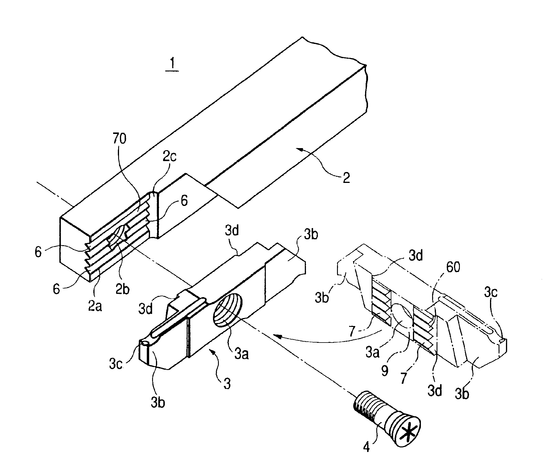
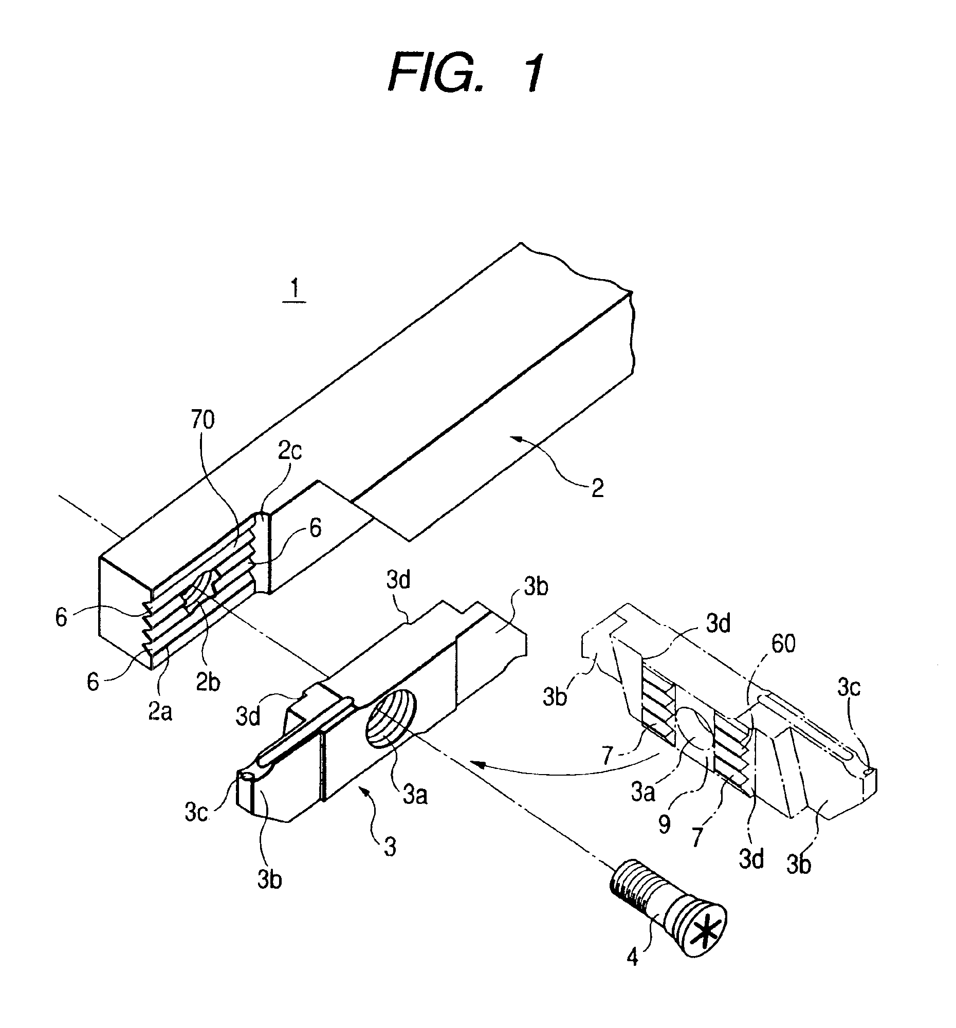
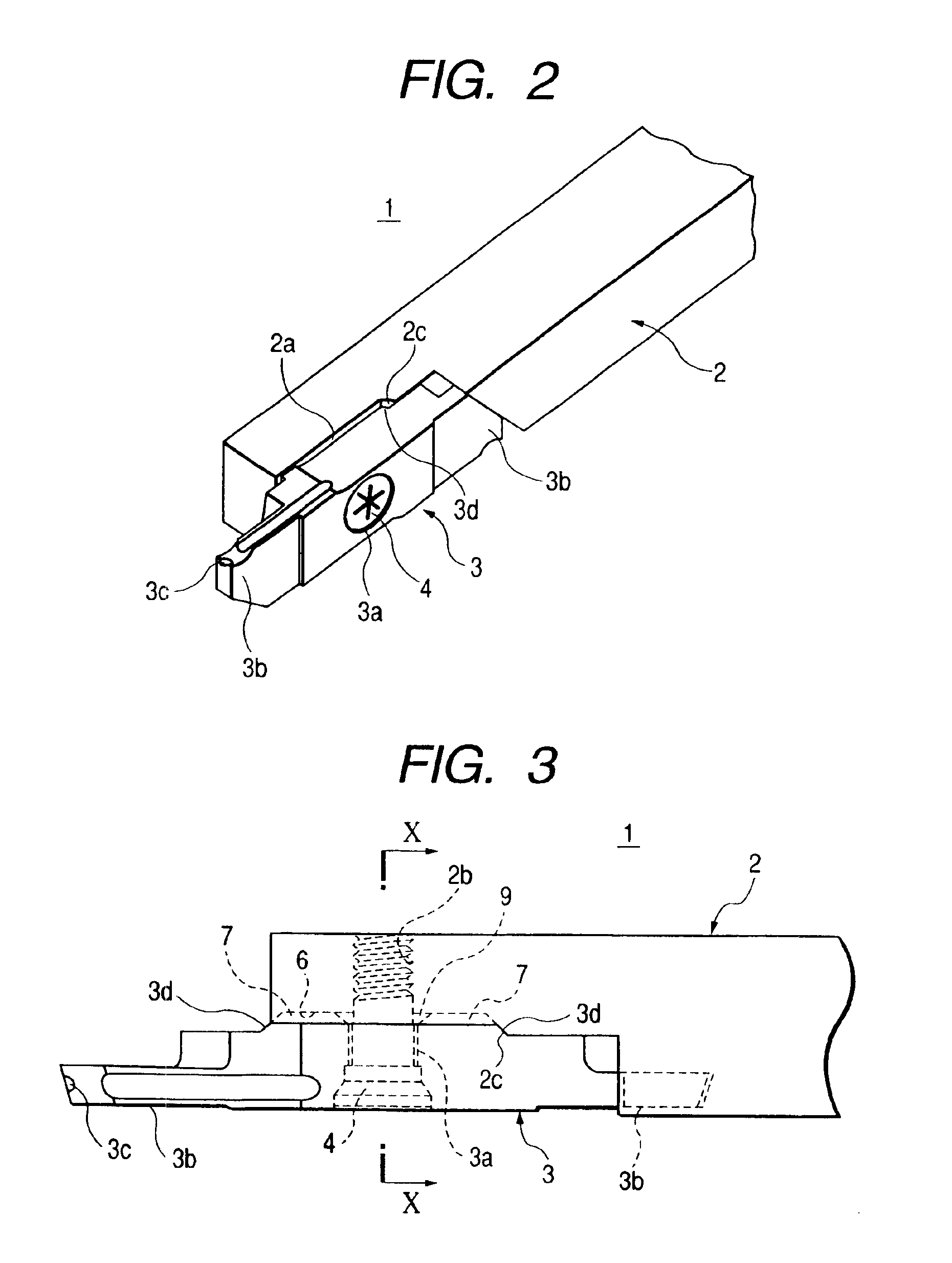
[0023]Referring to FIGS. 1 to 6, a first exemplary embodiment of the present invention will be described below. FIG. 1 is an exploded perspective view of a cutting tool, FIG. 2 is a perspective view of the cutting tool, FIG. 3 is a plan view of an essential part of the cutting tool, FIG. 4A is a cross-sectional view taken along line X—X of FIG. 3, FIG. 4B is a partially enlarged view of FIG. 4A, FIG. 5A is a transversal plan view showing an essential part of the cutting tool, FIG. 5B is a partially enlarged view of FIG. 5A, and FIG. 6 is a perspective view of an insert.

[0024]The cutting tool 1 is composed of three components, a holder 2, an insert 3 and a clamp screw 4 as clamping member, as shown in FIG. 1. The holder 2 has a tip mounting area in a top portion lowered by one step, in which a top end portion further lowered by one step in the tip mounting area is a tip mounting face 2a. On this tip mounting face 2a, four concave grooves 6, similar to a V-shape, are formed in paralle...


PUM

PropertyMeasurementUnit
thicknessaaaaaaaaaa
thicknessaaaaaaaaaa
thicknessaaaaaaaaaa

Abstract

A cutting tool has an insert shaped as a parallelogram that is detachably mounted by a clamp screw 4 on a tip mounting face of a holder. Concave grooves are formed like parallel stripes on the tip mounting face of the holder, and convex lines are formed on the abdominal face of the insert to be fitted in the concave grooves, so that the insert is clamped by the clamp screw to the holder in a state where the convex lines are fitted in the concave grooves on the tip mounting face.

Description

CROSS-REFERENCE TO RELATED APPLICATIONS[0001]This application claims the priority of Japanese Patent Application No. 2002-185267, filed on Jun. 25, 2002, in the Japanese Patent Office, the disclosure of which is incorporated herein in its entirety by reference.BACKGROUND OF THE INVENTION[0002]The present invention relates to an insert and a holder of a cutting tool. More particularly, the insert is brought into engagement with the holder with concave and convex grooves to provide a secure engagement.[0003]Conventionally, there is a cutting tool 104 in which an insert 102 having a basic form of parallelogram is detachably mounted by a clamp screw 103 as a clamping member on a tip mounting face 101 of a holder 100 (see FIG. 8). The holder 100 of this cutting tool 104 has the flat tip mounting face 101 provided with a female thread hole 105 into which the clamp screw 103 is screwed, and a restricting wall 106 protruding on the tip mounting face 101, for restricting the movement of the ...

Claims


Application Information

Patent Timeline
Patent Type & Authority Patents(United States)
IPC IPC(8): B23B27/00B23B27/08B23B27/16
CPCB23B27/08B23B2260/132Y10T407/25Y10T407/2248Y10T407/23Y10T407/22Y10T407/2274B23B27/16
Inventor INAYAMA, TAKASHI
Owner NGK SPARK PLUG CO LTD
Why Eureka
Try Eureka