Modified upper rear door hinge patch

a rear door and hinge technology, applied in the field of modified upper rear door hinge patch, can solve the problems of difficult to shape difficulty in forming the hss or uhss to design specifications, and the formability of the steel used to manufacture the interior center pillar structure to design specifications, etc., to improve the formability of the center pillar stiffener, improve the absorption of energy, and reduce the depth of the r

Inactive Publication Date: 2011-06-14
HONDA MOTOR CO LTD
View PDF22 Cites 25 Cited by
  • Summary
  • Abstract
  • Description
  • Claims
  • Application Information

AI Technical Summary

Benefits of technology

[0005]In accordance with another embodiment of the invention, a method for improving the formability of a center pillar stiffener comprises: (A) operatively connecting a modified upper rear door hinge patch to an upper rear door hinge patch attachment point on an outside surface of a center pillar stiffener; (B) wherein the attachment configuration creates a cavity between the upper rear door hinge patch and the center pillar stiffener; (C) thereby reducing the depth of a recess on an inside surface of the center pillar stiffener at the upper rear door hinge mating area.
[0006]In accordance with yet another embodiment of the invention, a method for improving the absorption of energy and reducing strain on center pillar structures in side impact collisions comprises: (A) operatively connecting a modified upper rear door hinge patch to an upper rear door hinge patch attachment point on an outside surface of a center pillar stiffener; (B) wherein the attachment configuration creates a cavity between the upper rear door hinge patch and the center pillar stiffener; (C) the upper rear door hinge patch absorbing energy transferred from a side impact collision.
[0007]In accordance with yet another embodiment of the invention, a method for improving door hinge mounting accuracy apart from the center pillar stiffener comprises: (A) operatively connecting a modified upper rear door hinge patch to an upper rear door hinge attachment point on an outside surface of a center pillar stiffener; wherein the attachment configuration aligns openings in the modified upper rear door hinge patch with openings in an exterior side body panel; (B) passing mounting members through openings in a door hinge device, through openings in the exterior side body panel, and through openings in the modified upper rear door hinge patch; (C) operatively securing the mounting members with a fastener; the fastener being operatively attached to the mounting members on an inside surface of the modified upper rear door hinge patch.

Problems solved by technology

The use of HSS or UHSS, however, presents difficulties with the formability of the steel used to manufacture the interior center pillar structures to design specifications.
This geometry makes it difficult to shape the HSS or UHSS to design specifications, and additionally creates problems with door hinge mounting accuracy that have previously been difficult to resolve.
The typical design for a center pillar support structure is also vulnerable to buckling or kinking during a side impact collision, causing damage to the vehicle's frame that is expensive and difficult to repair.
As a result, because the upper portion of the center pillar is smaller and narrower than at the pillar's base, it is not capable of absorbing as much energy as the lower portion of the pillar.

Method used


Image

  • Modified upper rear door hinge patch
  • Modified upper rear door hinge patch
  • Modified upper rear door hinge patch

Examples


Embodiment Construction

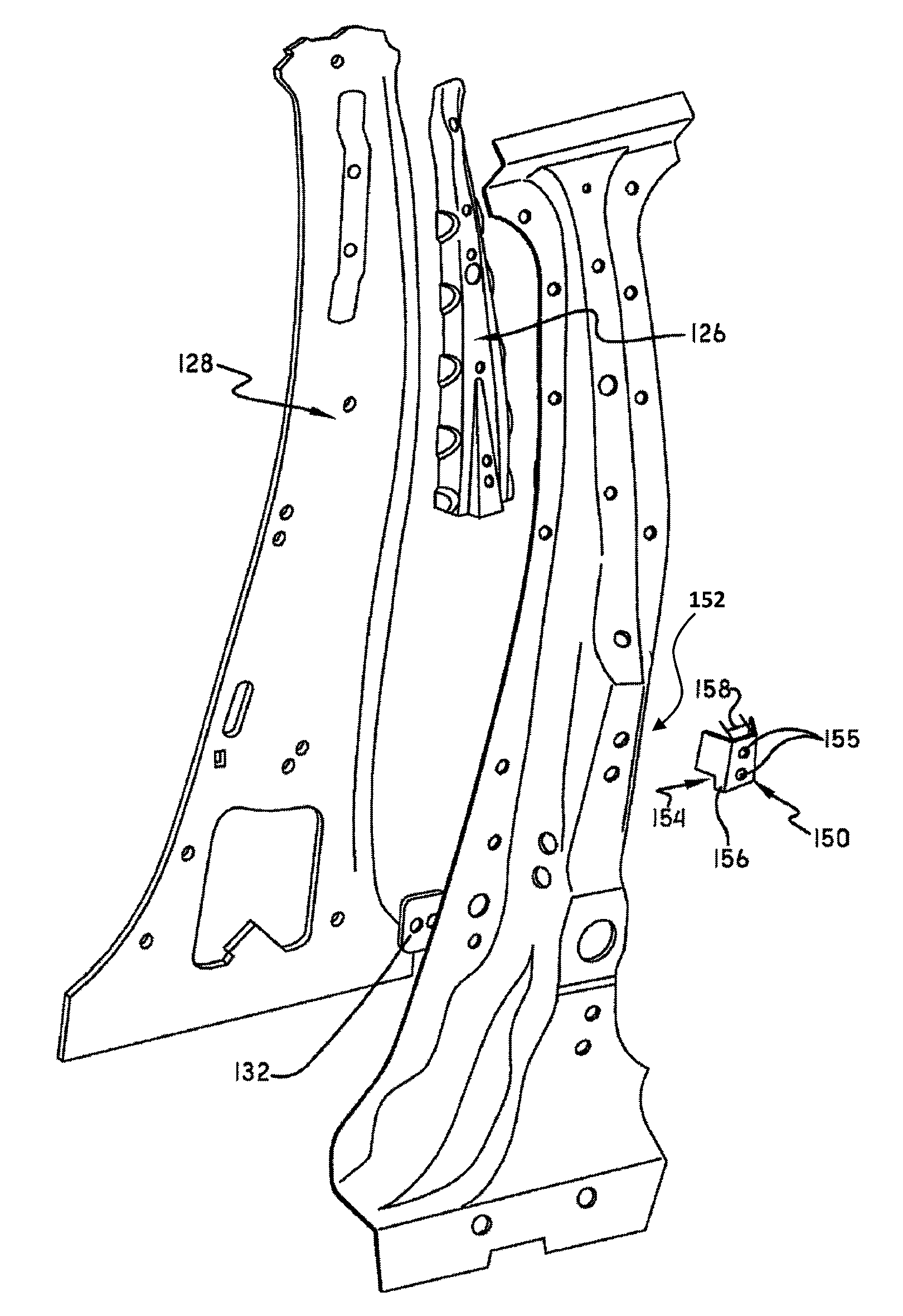
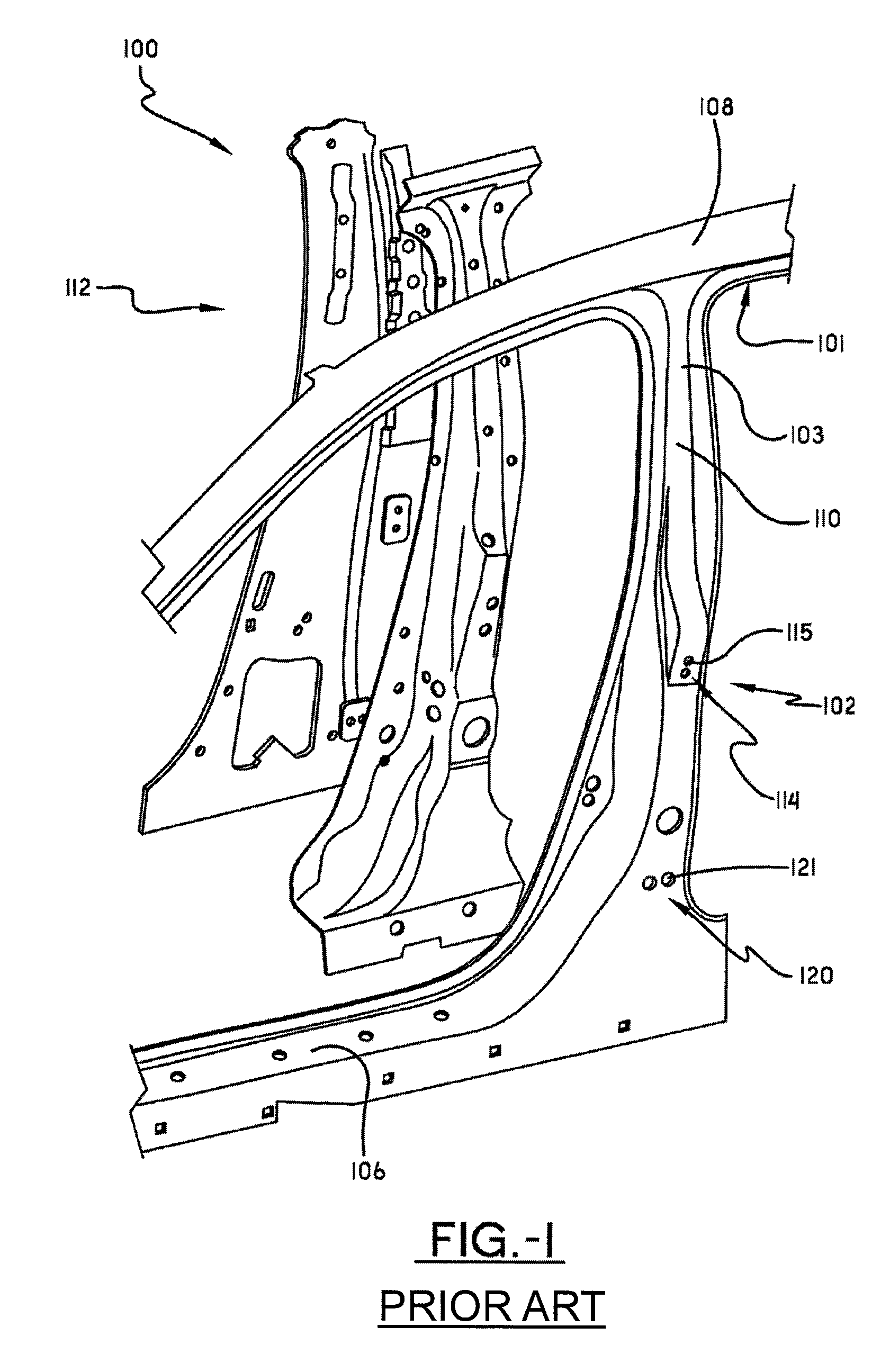
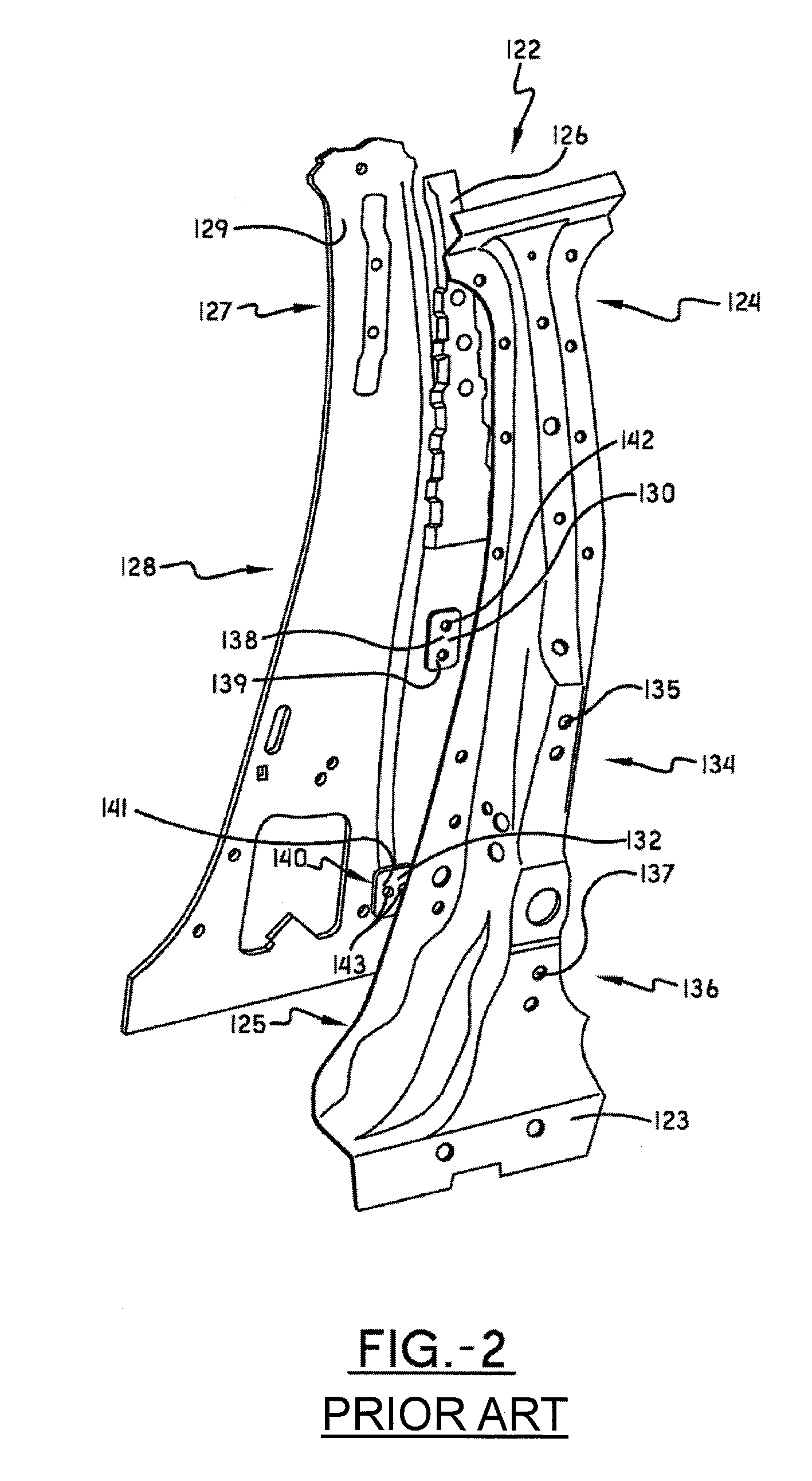
[0028]Referring now to the drawings, wherein the showings are for the purposes of illustrating embodiments of the invention only and not for the purposes of limiting the same, FIG. 1 illustrates a typical prior art side body structure 100 for an automotive vehicle 105. Most side body structures consist of an exterior side body panel 102 and an interior center pillar structure 122; the two structures being operatively connected in such a fashion that the vehicle's side body structure 100 provides support for the vehicle's doors 107 and roof (shown but not referenced), while also providing some measure of protection to the vehicle's passengers from weather, road debris, and side impact collisions.

[0029]The exterior side body panel 102 shown in FIG. 1 has a lower sill 106 running horizontally between a front wheel well (not shown) and a rear wheel well (not shown) along a lengthwise side of the vehicle 105. The exterior side body panel 102 also has an upper rail 108 that runs generally...


PUM


Abstract

The attachment of a modified upper rear door hinge patch to the outside surface of a center pillar stiffener creates an energy absorbing cavity that: 1) reduces the chances that the center pillar stiffener will buckle or kink in a side impact collision, and 2) improves door mounting accuracy apart from the center pillar stiffener, and 3) improves the formability of the steel used in the manufacture of center pillar stiffeners.

Description

I. BACKGROUND OF THE INVENTION[0001]The use of center pillar support structures in an automotive vehicle's side body structure is well known in the art. The typical center pillar support structure consists of one or more vertically positioned metal pieces extending from the vehicle's floor pan and rocker panel up to the vehicle's roof. The center pillar support structure is capable of supporting rear door hinge devices pivotally attached to a rear door, and usually accepts a striker that engages a latch on a vehicle's front door in order to releasably maintain the front door in a closed position. Generally, center pillar structures also define the areas of access to the passenger compartment through the front and rear doors, act as a columnar support structure between a vehicle's upper roof rail and lower side sill, and protect the vehicle's passengers against a side impact collision. Oftentimes, the center pillar structure provides additional protection against side impacts by inte...

Claims


Application Information

Patent Timeline
Patent Type & Authority Patents(United States)
IPC IPC(8): B62D25/02
CPCB62D25/04
Inventor ONUMA, TAKASHI
Owner HONDA MOTOR CO LTD
Why Eureka
Try Eureka