Chip mounting method and system for guiding robot vision

A robot vision and chip mounting technology, which is applied in semiconductor/solid-state device manufacturing, electrical components, circuits, etc., and can solve problems such as poor flexibility and low chip mounting accuracy.

Active Publication Date: 2018-11-06
HUNAN UNIV
View PDF3 Cites 26 Cited by
  • Summary
  • Abstract
  • Description
  • Claims
  • Application Information

AI Technical Summary

Problems solved by technology

[0005] Aiming at the technical problems of low chip mounting precision and poor flexibility in the prior art, the present invention provides a robot vision-guided chip mounting method and system

Method used


Image

  • Chip mounting method and system for guiding robot vision
  • Chip mounting method and system for guiding robot vision
  • Chip mounting method and system for guiding robot vision

Examples


Embodiment Construction

[0115] The technical solutions in the present invention are clearly and completely described below in combination with the accompanying drawings in the embodiments of the present invention. Obviously, the described embodiments are only some of the embodiments of the present invention, not all of them. Based on the embodiments of the present invention, all other embodiments obtained by persons of ordinary skill in the art without creative efforts fall within the protection scope of the present invention.

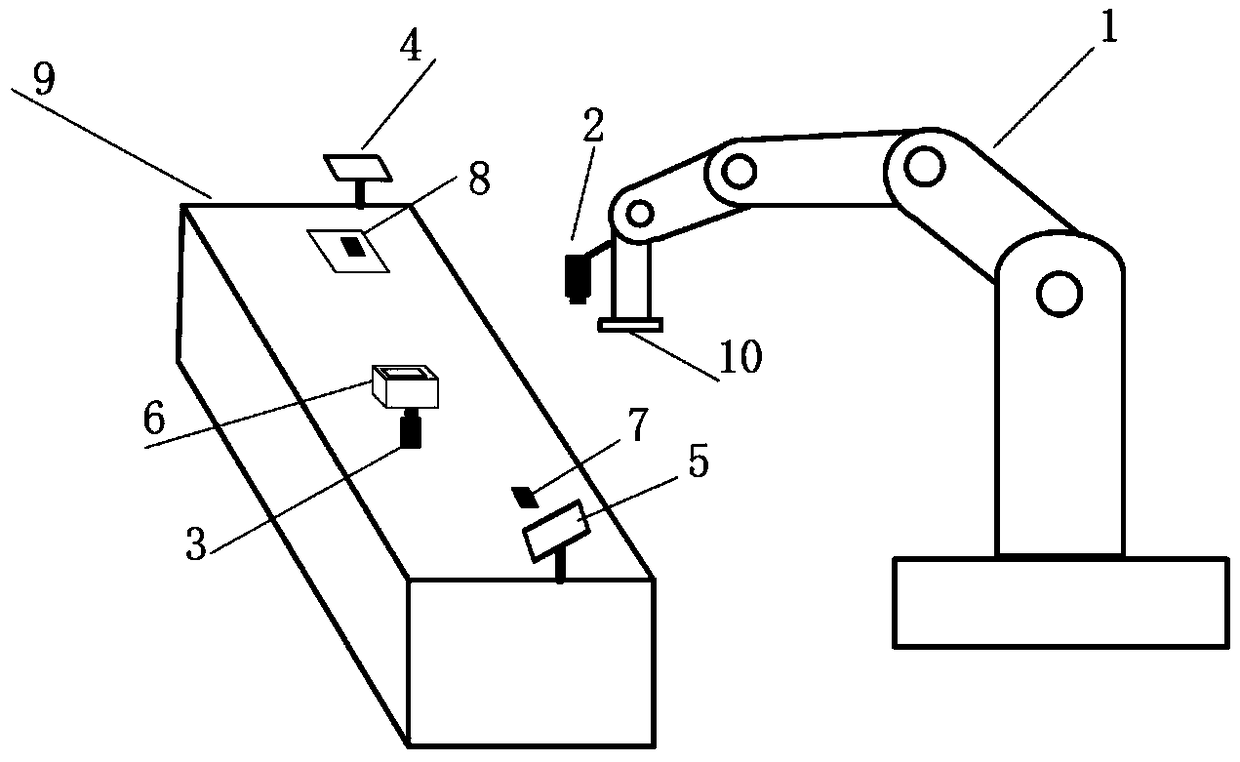
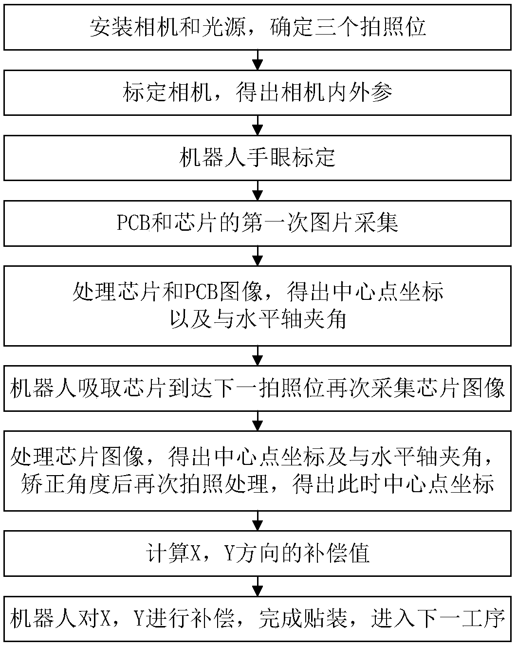
[0116] Such as figure 1 and figure 2 As shown, a chip mounting method guided by robot vision provided by the present invention comprises the following steps:

[0117] Step (1): The installation of the camera and the determination of the photographing position;

[0118] The first industrial camera is installed on the hand of the six-axis robot. The first industrial camera moves with the hand and has a wider field of view for taking pictures. It is used for the first image a...


PUM


Abstract

The invention discloses a chip mounting method and system for guiding robot vision. A second industrial camera is additionally arranged in each of a PCB placing area and a chip placing area; a robot is used for absorbing chips to be moved to the positions of the second industrial cameras, the images of the absorbed chips are shot, and angular difference between the included angle of the chip mounting area and a horizontal axis and the included angle of the chips after the chips are absorbed and the horizontal axis is compared so that an end actuator rotates at the position of P3 in the angulardifference, angular compensation is carried out, compensation is carried out on X axis and Y axis, the sliding error generated when the chips are absorbed or in the moving process after the chips areabsorbed is improved, and the mounting precision is improved; moreover, a six-axis robot is adopted, due to the fact that the six-axis robot has higher degree of freedom and flexibility, the chip mounting inside workpieces such as cavities is realized, and flexible production is achieved; and then, first industrial cameras are arranged on the hands of the robot, and the robot is easier to move, so that the visual control method based on position is higher in flexibility and wider in range of application.

Description

technical field [0001] The invention belongs to the technical field of robot vision assembly, and in particular relates to a chip mounting method and system guided by robot vision. Background technique [0002] China is a big electronics manufacturing country. According to the data from the National Bureau of Statistics, by the end of 2017, there were nearly 15,000 electronics manufacturing companies in China. The main income of the electronics manufacturing industry was nearly 10 trillion yuan. The increase in fixed assets has reached more than 20% for many years. In addition, electronic assembly has the characteristics of small workpiece size, various types, complex assembly process, and high assembly precision requirements. Therefore, in the entire electronic manufacturing process, the assembly work time accounts for about 40%-60% of the total electronic manufacturing time. The assembly workload About 50%-70% of the total workload. [0003] At present, the main equipmen...

Claims


Application Information

Patent Timeline
Patent Type & Authority Applications(China)
IPC IPC(8): H01L21/50H01L21/67
CPCH01L21/50H01L21/67126
Inventor 王耀南马聪贾林彭伟星吴昊天钱珊珊张煜田吉委李娟慧
Owner HUNAN UNIV
Why Eureka
Try Eureka