Electronic component mounting apparatus, height detection method for electronic component, and optical-axis adjustment method for component height detection unit

a technology for electronic components and mounting apparatuses, which is applied in the direction of mechanical measuring arrangements, instruments, and using mechanical means, etc., can solve the problems of difficult to accurately detect a change in the received light quantity, the height size of such a small component cannot be accurately detected, and the price of line sensors is much higher than photoelectric sensors, so as to improve the mounting accuracy of electronic components in the electronic component mounting apparatus, reduce the beam, and accurately detect the

Inactive Publication Date: 2009-09-10
PANASONIC CORP
View PDF2 Cites 24 Cited by
  • Summary
  • Abstract
  • Description
  • Claims
  • Application Information

AI Technical Summary

Benefits of technology

[0054]According to the present invention, by the inclusion of a projection-side orifice that narrows the projection spot diameter and a reception-side orifice that narrows the light-reception spot diameter, influences of diffraction of a light beam, e.g. laser beam, can be reduced. Furthermore, by the inclusion of a light-reception-sensitivity setting unit, such as an amplification unit for setting light-reception sensitivity in the beam receiver to an enhanced state as compared with cases in which those orifices are not provided, changes in the received light quantity due to interception of the light beam by an electronic component or a component holding member can be detected clearly. Thus, even if the electronic component is a small component, the component height can be accurately detected, so that the mounting accuracy for electronic components in the electronic component mounting apparatus can be improved.
[0055]Further, any height position detection error due to response delay in the component height detection unit is eliminated by taking average values of height positions of the component holding member detected in down and up motions of the component holding member. Thus, the height of the electronic component can be accurately measured.
[0056]Furthermore, since the received light quantity is decreased with interposition of an optical filter in the optical-axis adjustment of the component height detection unit, it becomes practicable to carry out the optical-axis adjustment as the light-reception sensitivity is kept improved. Further, since decreasing the received light quantity with an optical filter as shown above makes it possible to digitally grasp a time point when the beam receiver has come to a complete light-reception state, it becomes practicable to achieve an accurate optical-axis adjustment.

Problems solved by technology

Therefore, changes in received light quantity that decreases due to light interception by the small component are only minute ones, making it possible difficult to accurately detect a change in the received light quantity.
Also, since light diffracted at end portions of a small component is received by the beam receiver, it is impossible to accurately detect a time point when the laser beam is intercepted by the small component, posing a problem that the height size of such a small component cannot be accurately detected in some cases.
It is noted that although using a line sensor including a CCD camera enables a comparatively accurate detection of such small components, yet the line sensor is much higher in price than photoelectric sensors, being disadvantageous in terms of cost.
Therefore, increasing the up / down speed of the nozzle causes occurrence of a noticeable response delay, with the result that the detected encoder value is shifted by the response delay from a true encoder value resulting at the time point when the received light quantity of the beam receiver has reached the certain threshold value.
However, the shift amount of the encoder value varies depending on such conditions as the down-motion speed of the nozzle and the height of the picked-up electronic component, so that it is difficult to accurately set a corrected value corresponding to the individual conditions.
Moreover, electronic components that fall outside the conditions are unmanageable with preset corrected values.

Method used


Image

  • Electronic component mounting apparatus, height detection method for electronic component, and optical-axis adjustment method for component height detection unit
  • Electronic component mounting apparatus, height detection method for electronic component, and optical-axis adjustment method for component height detection unit
  • Electronic component mounting apparatus, height detection method for electronic component, and optical-axis adjustment method for component height detection unit

Examples


first embodiment

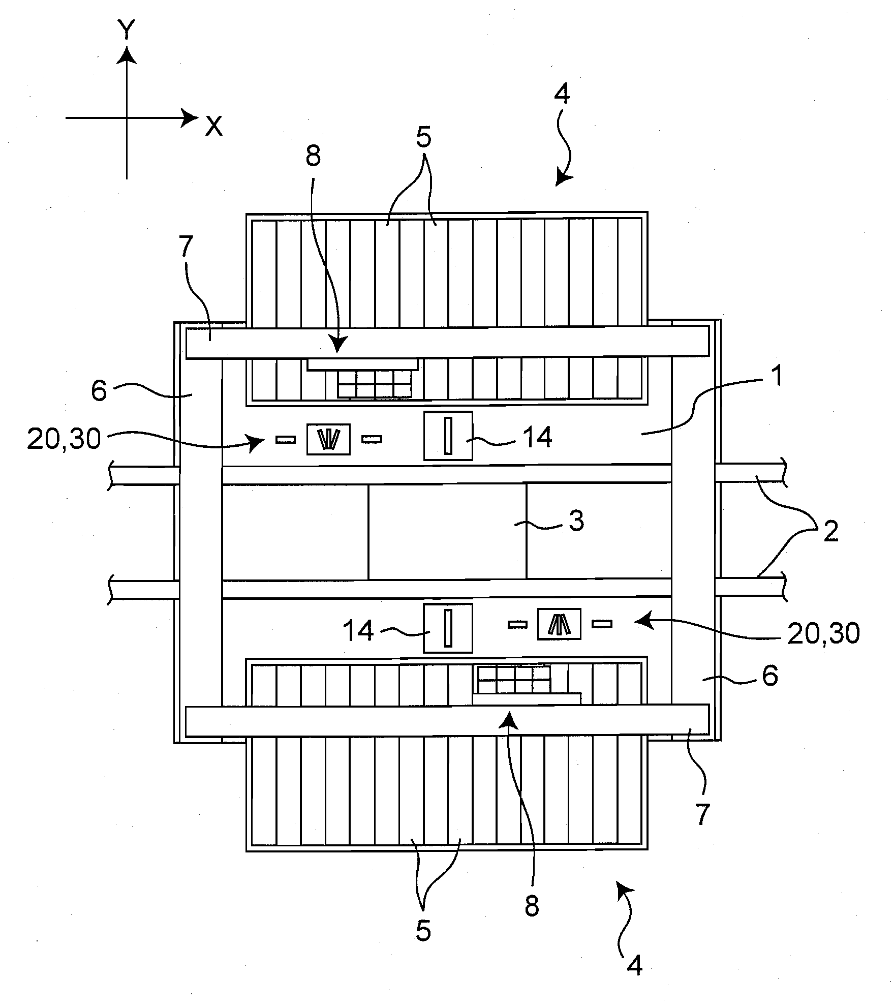
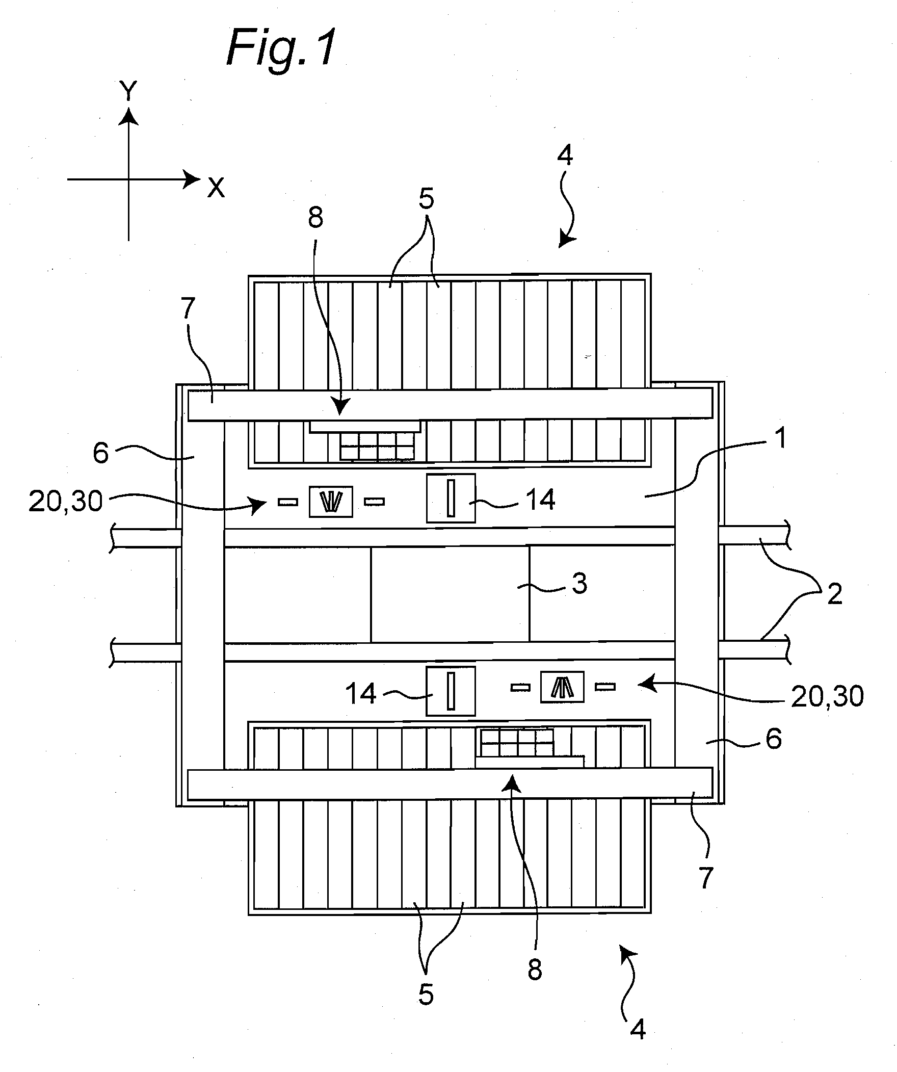
[0083]General construction of an electronic component mounting apparatus according to a first embodiment of the present invention is described with reference to a schematic plan view of an electronic component mounting apparatus 100 shown in FIG. 1. As shown in FIG. 1, a conveyance guide 2 is placed at a generally center on a base 1. The conveyance guide 2 is an example of a board conveyance and positioning unit for conveying a board (circuit board) 3 as a mounting object, onto which an electronic component is to be mounted, and positioning the board to a specified position on the base 1. In this first embodiment, it is assumed that the conveyance direction of the board 3 is an X direction and a direction orthogonal to that within a horizontal plane is a Y direction.

[0084]Also, as shown in FIG. 1, component feed units 4 are placed on both sides of the conveyance guide 2 in the Y direction, and a plurality of tape feeders 5 are removably provided in arrays. A pair of Y tables 6 is pl...

second embodiment

[0138]The present invention is not limited to the foregoing first embodiment, and may be embodied in other various modes. For example, an electronic component mounting apparatus according to a second embodiment of the present invention, while including a sensor unit substantially similar in construction to the sensor unit 20 of the first embodiment, is intended to further improve the detection accuracy by detecting component height with a technique different from that of the first embodiment. Accordingly, in the following description, constituent members having the same construction as those of the sensor unit 20 of the first embodiment are designated by the same reference numerals and their description is omitted.

[0139]First, a schematic structural view showing the structure of a sensor unit 220, which is an example of the component height detection unit included in the electronic component mounting apparatus of the second embodiment, is shown in FIG. 11. As shown in FIG. 11, the s...

third embodiment

[0163]Next, as a third embodiment of the invention, an optical-axis adjustment method for the sensor unit included in the electronic component mounting apparatus of the first or second embodiment is described below with reference to schematic explanatory views shown in FIGS. 15 and 16.

[0164]The optical-axis adjustment in such a sensor unit 20 (or sensor unit 220) is performed by adjusting the position or inclination of the beam projector 21 and the beam receiver 22 so as to provide a state that the laser beam Q projected generally horizontally from the beam projector 21 is perfectly received by the beam receiver 22, i.e., a state that the laser beam passes through the entire hole portion of the reception-side orifice 22a of the beam receiver 22 so that a laser beam of a specified light-reception spot diameter can be received by the beam receiver 22.

[0165]More specifically, first, as shown in FIG. 15, an optical filter 89 is placed on an optical axis between the beam projector 21 and...


PUM


Abstract

An electronic component mounting apparatus includes a beam projector for projecting a laser beam, a beam receiver which is placed in opposition to the beam projector and which receives a laser beam projected from the beam projector, a light-reception-sensitivity setting unit for adjusting light-reception sensitivity of the beam receiver, a projection-side orifice provided in the beam projector to narrow a projection spot diameter of the laser beam, and a reception-side orifice provided in the beam receiver to narrow a light-reception spot diameter, where the light-reception sensitivity of the beam receiver is improved. As a result, an electronic component mounting apparatus capable of accurately detecting height size of small components by using a relatively inexpensive photoelectric sensor can be provided.

Description

TECHNICAL FIELD[0001]The present invention relates to an electronic component mounting apparatus for picking up an electronic component from an electronic component feed unit by a component holding member and mounting the electronic component onto a board or other mounting object. In particular, the present invention relates to an electronic component mounting apparatus including a component height detection unit for detecting a height or thickness dimension of an electronic component held by a component holding member.BACKGROUND ART[0002]In the field of electronic component mounting that electronic components are picked up from an electronic component feed unit by a nozzle, that is a component holding member, and mounted onto a board or other mounting object, it is practiced to measure the height size of the electronic component picked up by the nozzle for accurate mounting of the electronic component onto the board or other mounting object. The measured height size of the electron...

Claims


Application Information

Patent Timeline
Patent Type & Authority Applications(United States)
IPC IPC(8): G01B11/02G06F15/00
CPCH05K13/0452H05K13/0413H05K13/0812
Inventor HIYOSHI, MASANORISAHO, HIDEHIROYAMASAKI, NOBORUENDO, TADASHI
Owner PANASONIC CORP
Why Eureka
Try Eureka