Motor using permanent magnet

a permanent magnet and motor technology, applied in the field of motors, can solve the problems of reduced motor thrust, inability to achieve high-speed driving, and ineffective utilization of the magnetic flux of each permanent magnet b>64/b>, so as to reduce the heat generated in the motor, reduce the magnetic flux, and improve the output thrust

Inactive Publication Date: 2005-11-01
OKUMA CORP
View PDF14 Cites 31 Cited by
  • Summary
  • Abstract
  • Description
  • Claims
  • Application Information

AI Technical Summary

Benefits of technology

[0029]With this structure, the magnetic flux can flow smoothly along the teeth core to the magnetic yokes 3a and 3b and does not cross the electromagnetic steel plates. As a result, reduction in the magnetic flux is prevented and the output thrust can be improved, and generation of iron loss due to an eddy current can be inhibited, and, consequently, heat generated in the motor is reduced.

Problems solved by technology

However, the driving frequency for controllably driving this example motor is approximately six times that of the two pole permanent magnet type linear motor, and, because of the limit of the driving frequency and inductance of the winding, in general, high speed driving is not possible.
On the other hand, in a synchronization type linear motor of the related art, there is a problem in that the magnetic flux of each permanent magnet 64 cannot be effectively utilized.
For a similar reason, in the other mover salient poles 65, effective magnetic flux cannot be sufficiently obtained, resulting in a problem in that a motor thrust is reduced, even when the motor current is suitably applied.
Another problem is that although a maximum magnetic flux density of an electromagnetic steel plate of the mover salient pole 65 has a large value of about 1.7 Tesla, a maximum magnetic density of the stator magnetic pole is about 1.0 Tesla, even when a rare earth metal which has a large remaining magnetic flux density is used.
Therefore, there is a problem in that, structurally, the magnetic flux density cannot be increased.
Another problem is that when the linear motor has a relatively long driving range, the cost of the linear motor is significantly increased because the amount of permanent magnet mounted in the stator 61 is proportional to the length of the motor driving range.
Another problem is that when the linear motor is applied to feed driving of a machine tool or the like, iron powder or the like may be present in the surrounding environment of the linear motor, and therefore, the permanent magnet 64 must be carefully covered to prevent attachment of the iron powder or the like.
There is also a problem in that, because the length of the magnet portion is relatively long, the cost of the necessary cover is increased.
In the linear motor of the related art described above, however, there are disadvantages, such as those that are next described.
Because of this, there is a problem in that the magnetic flux is saturated in this area and the motor thrust is reduced.
As a result, there remains with this art a problem in that an eddy current flows in the electromagnetic steel plates forming the magnetic poles 5 and 6, iron loss is generated corresponding to the electrical resistance of the electromagnetic steel plates, and an undesirable amount of heat is generated in the motor.
Similarly, because a magnetic flux is generated across the direction in which the electromagnetic steel plates are layered, a non-magnetic insulating coating applied on a surface of each electromagnetic steel plate forming the magnetic poles 5 and 6 and magnetic yokes 3a and 3b of the mover 3 and an air layer between electromagnetic steel plates would act as a magnetic insulating portion, resulting in a problem in that, because the magnetic flux flowing through each of the magnetic poles 5 and 6 is reduced, the output thrust is reduced.

Method used


Image

  • Motor using permanent magnet
  • Motor using permanent magnet
  • Motor using permanent magnet

Examples


first preferred embodiment

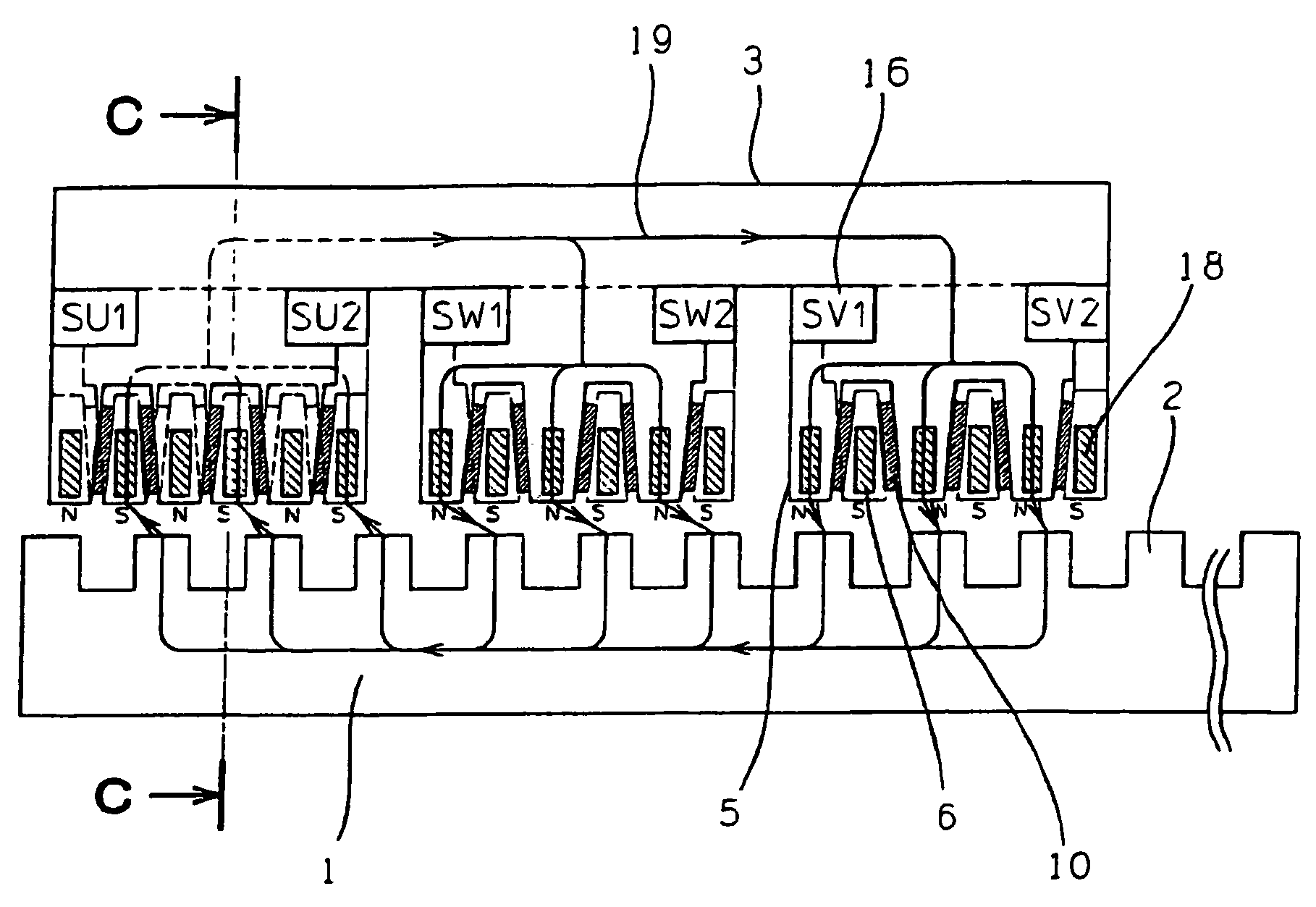
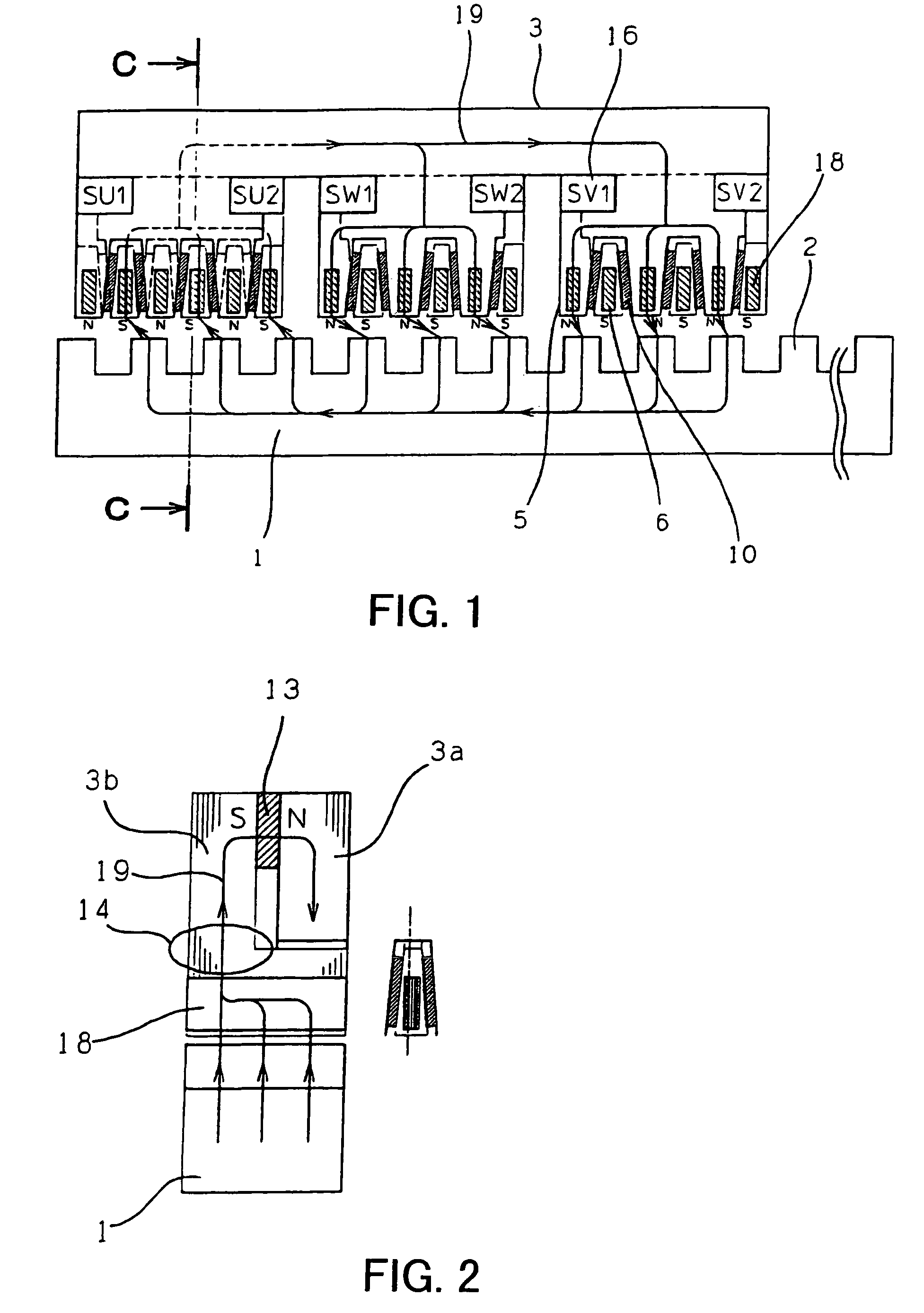
[0049]FIGS. 1, 2, and 3 show a permanent magnet linear motor according to a first preferred embodiment of the present invention. FIG. 2 is a diagram showing a C—C cross section of FIG. 1, and FIG. 3 is a side view and a bottom view of a mover 3 of FIG. 1. The first preferred embodiment will now be described referring to FIGS. 1, 2, and 3.

[0050]In FIGS. 1, 2, and 3, reference numeral 3 represents a mover, reference numeral 3a represents an N pole magnetic yoke, and reference numeral 3b represents an S pole magnetic yoke. The N pole magnetic yoke 3a and the S pole magnetic yoke 3b are formed by layering electromagnetic steel plates. Reference numeral 16 represents a three-phase AC winding, symbols SU1 and SU2 represent U-phase windings, symbols SV1 and SV2 represents V-phase windings, and symbols SW1 and SW2 represent W-phase windings. Reference numeral 5 represents an N magnetic pole, reference numeral 6 represents an S magnetic pole, and reference numeral 10 represents an auxiliary ...

second preferred embodiment

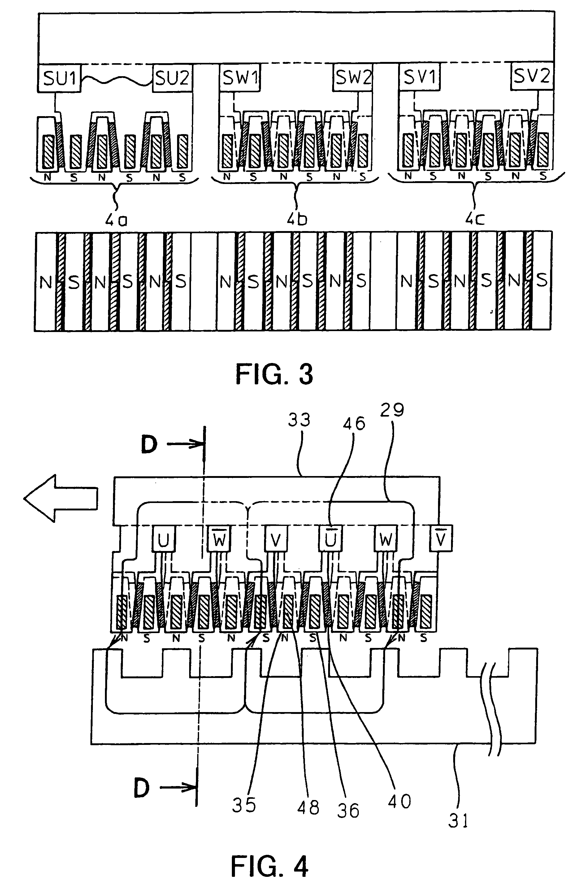
[0055]FIGS. 4, 5, and 6 show a linear motor according to a second preferred embodiment of the present invention. FIG. 5 is a diagram showing a D—D cross section in FIG. 4 and FIG. 6 is a side and bottom views of a mover 33. Similar as in the first preferred embodiment, in this motor, a three-dimensional magnetic path is generated between the mover 33 and the stator 31, but the linear motor of the second preferred embodiment has a different configuration from the linear motor of the first embodiment. The second preferred embodiment will now be described referring to FIGS. 4, 5, and 6.

[0056]In FIGS. 4, 5, and 6, reference numeral 33 represents a mover, reference numeral 33a represents an N pole magnetic yoke, and reference numeral 33b represents an S pole magnetic yoke. The N pole magnetic yoke 33a and the S pole magnetic yoke 33b are formed by layering electromagnetic steel plates. Reference numeral 46 represents a three-phase AC winding and symbols indicating U-phase, V-phase, and W...


PUM


Abstract

A motor which uses a permanent magnet is provided in which output thrust is improved by increasing a magnetic saturation limit and preventing reduction in magnetic flux and generation of heat is reduced by inhibiting generation of an eddy current in a magnetic pole. An N magnetic pole is formed such that its width increases as the distance from a stator increases on a side of an N pole magnetic yoke and an S magnetic pole is formed such that its width increases as the distance from the stator increases on a side of an S pole magnetic yoke. With this structure, a saturation limit of magnetic flux at an entrance of yoke which is a connection section between the N magnetic pole and the N pole magnetic yoke is increased and motor thrust is improved.

Description

BACKGROUND OF THE INVENTION[0001]1. Field of the Invention[0002]The present invention relates to a motor which uses a permanent magnet, and particularly to a motor structure suitable for a linear motor.[0003]2. Description of the Related Art[0004]FIG. 13 is a diagram showing a synchronization type linear motor according to related art. FIGS. 14, 15, 16, and 17 are diagrams showing a linear motor according to related art disclosed by the present applicant in Japanese Patent No. 3,344,645, which provides a solution to certain problems associated with a synchronization type linear motor. FIG. 15 is a diagram showing a cross section AA of FIG. 14 and FIG. 16 is a diagram showing a cross section BB of FIG. 14. FIG. 17 is a diagram showing a mover 3 seen from the side (side view) and from the bottom (bottom view).[0005]Characteristics of a synchronization type linear motor according to the related art will now be described. In FIG. 13, reference numeral 63 represents a mover, reference nu...

Claims


Application Information

Patent Timeline
Patent Type & Authority Patents(United States)
IPC IPC(8): H02K41/03H02K21/44H02K21/00
CPCH02K21/44H02K41/03
Inventor KAWAI, YOICHI
Owner OKUMA CORP
Why Eureka
Try Eureka