
Cordless, powered surgical tool

a surgical tool and cordless technology, applied in the direction of motor/generator/converter stopper, electronic commutator, dynamo-electric converter control, etc., can solve the problems of invariably repetitive force of the blade, saw blade engages in repetitive back and forth action, and limit of other cordless surgical tools, so as to reduce the noise generated by the tool, the effect of easily selecting the maximum speed of the tool

Inactive Publication Date: 2005-11-01
STRYKER CORP
View PDF16 Cites 101 Cited by
  • Summary
  • Abstract
  • Description
  • Claims
  • Application Information

AI Technical Summary

Benefits of technology

[0010]This invention relates to a cordless powered surgical tool with a control assembly that governs the initial operating speed of the tool so as to reduce the noise generated by the tool and the wear to which its components are exposed. This invention also relates to a control assembly for a surgical tool that has a trigger assembly that allows the surgeon to easily select the maximum speed of the tool.

Problems solved by technology

However, there are limitations associated with other cordless surgical tools, specifically, saws.
One of these limitations is associated with the fact that, by the very nature of its method of use, a saw blade engages in repetitive back and forth action.
As a result of this motion, the blade is invariably repetitively forced against components of the coupling assembly that holds the blade to the saw.
This component contact results in an appreciable amount of noise being generated when a saw is actuated.
This noise, at a minimum, can make it difficult to hear other sounds in an operating room.
This noise can further be distracting to the surgeon and serve as one of the environmental factors that contribute to the stress surgical personnel experience when performing a procedure.
While this method has proven somewhat successful in reducing tool-generated noise, it requires the surgeon to concentrate on the extent he / she has depressed the trigger integral with the tool.
Thus, the surgeon has to devote some attention to the trigger setting; this may distract from the surgeon's ability to concentrate on other aspects of performing the surgical procedure.
It should also be apparent that, in comparison to a high speed tool, the lower speed tool is less powerful and may not be able to cut tissue as fast.
In some instances, the lower speed tool may not even have the power to perform the task that can be accomplished with the higher speed tool.
This near duplication adds to the expense associated with providing a surgical facility.

Method used


Image

  • Cordless, powered surgical tool
  • Cordless, powered surgical tool
  • Cordless, powered surgical tool

Examples


Embodiment Construction

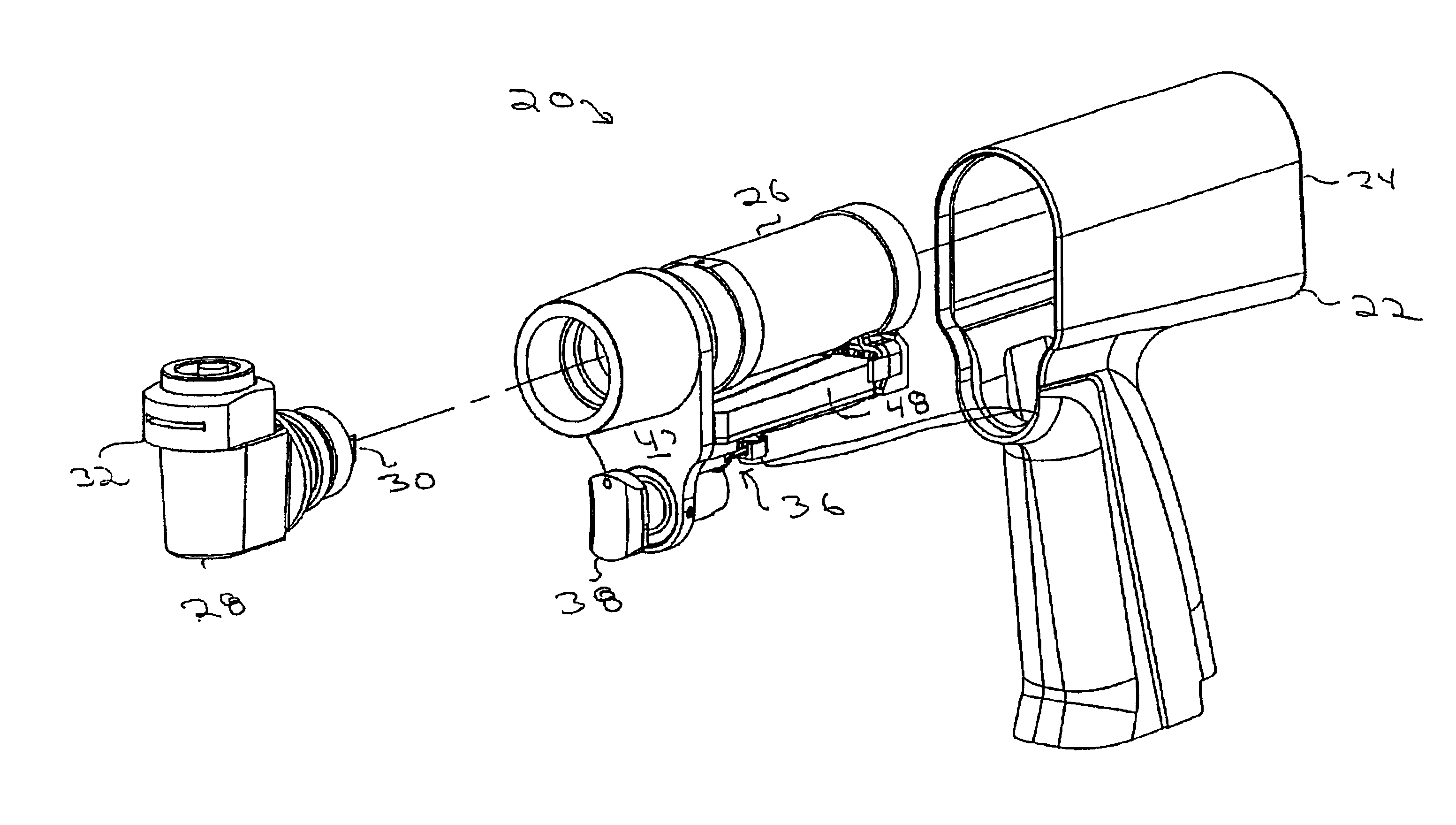
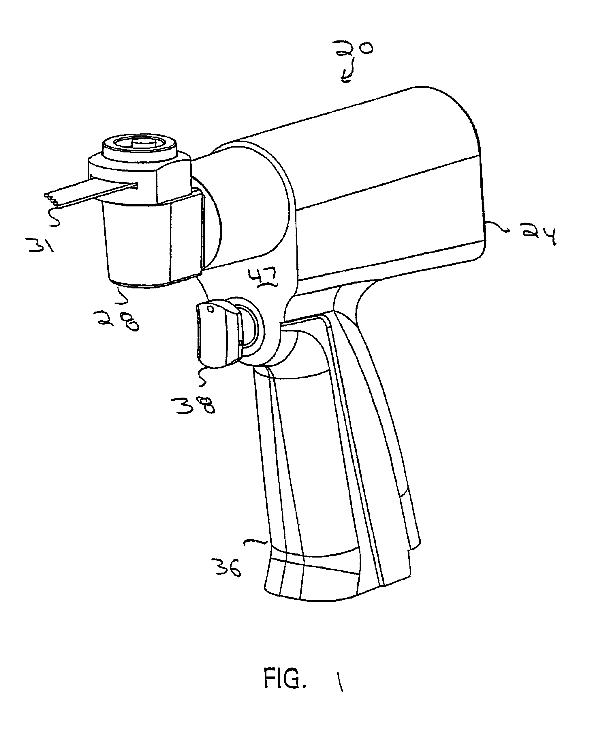
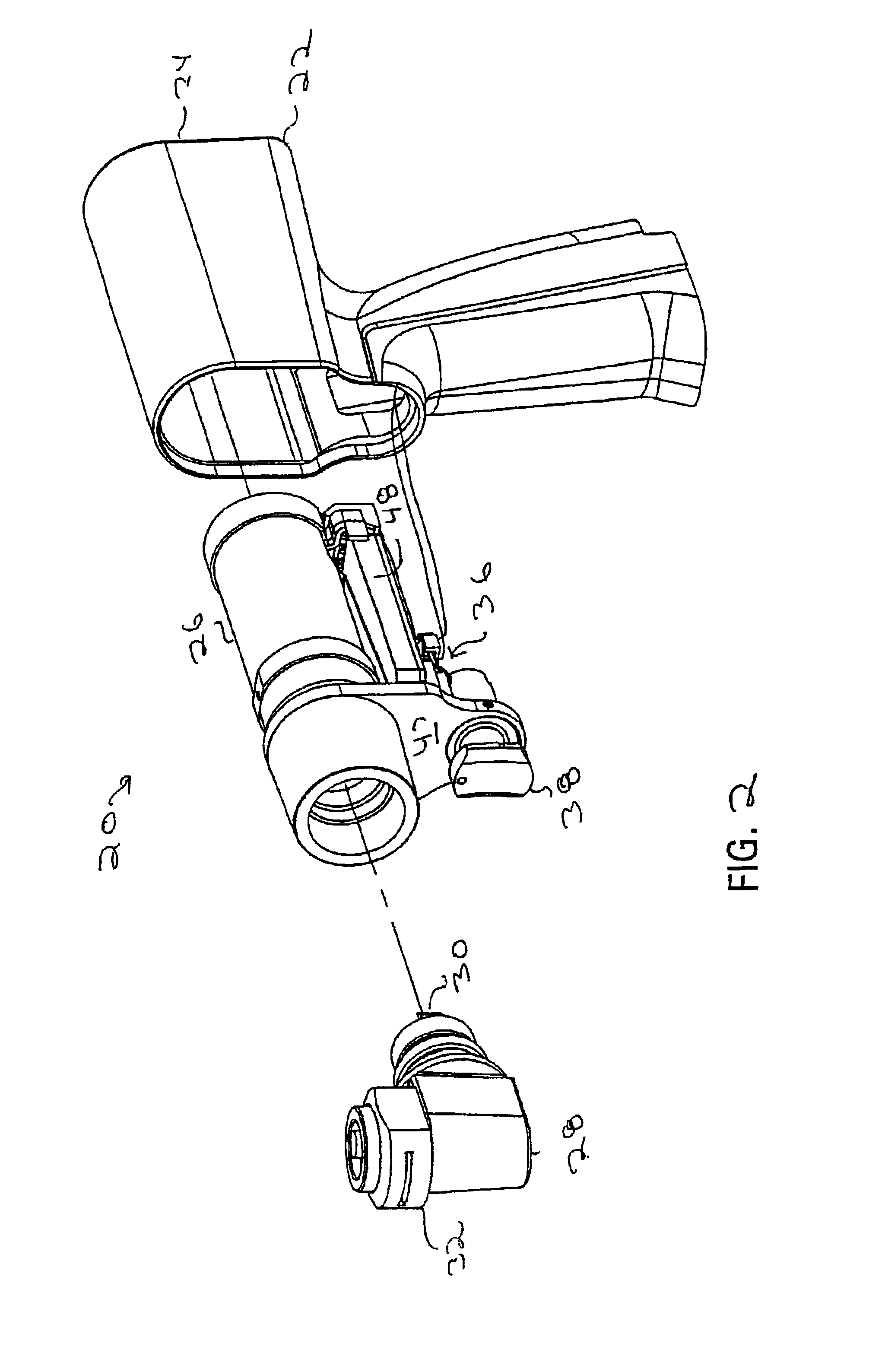
[0023]FIGS. 1 and 2 illustrate the basic features of a powered surgical tool 20 that is constructed in accordance with this invention. Tool 20 is a sagittal saw. It should, of course be recognized that other tools such as reciprocating saws, drills, reamers and wire drivers may embody the features of this invention. Tool 20 includes a housing 22 that contains most of the other components of the tool. Housing 22 has an upper portion 24 in which contains a DC driven, variable speed motor 26. A sagittal head 28 extends forward from an opening in the housing upper portion 24. Fitted to the sagittal head 28 are a linkage assembly 30 and a coupling assembly 32. The linkage assembly 30 is connected to the output shaft of the motor 26 and the coupling assembly 32. The linkage assembly 30 transfers and converts the rotary motion of the motor shaft to the coupling assembly so that the coupling assembly moves in an oscillatory pattern. The coupling assembly 32 is designed to releasably hold a ...


PUM


Abstract

A powered tool for performing surgical procedures. The tool includes a handpiece in which a power generating unit is housed. A control member is mounted to the handpiece. The control member is mounted to the handpiece so that the orientation of the control member can be selectively set relative to the point to which it is mounted to the handpiece and so it can move relative to a reference point on the handpiece. A control module monitors the orientation of the control member and its position relative to the reference point. Based on the control member orientation and position, the control module generates signals to regulate the operation of the power generating unit. When the power generating unit is a motor, the control module generates signals to ensure that the maximum speed at which the motor can be driven is less than the no load speed.

Description

FIELD OF THE INVENTION[0001]The invention of this application relates generally to a cordless, battery operated powered surgical tool. More particularly, the invention of this application relates to a cordless powered surgical tool, such as a surgical saw, that can be selectively configured for the preferences of individual surgeons and that is relatively quiet to operate.BACKGROUND OF THE INVENTION[0002]The cordless powered surgical tool has become an important instrument for performing a number of different surgical procedures. Generally, this tool includes a handpiece in which an electrically driven motor is housed. Power to energize the motor is supplied by a battery that is usually removably attached to the handpiece. A gear assembly and a coupling assembly transfer the rotary power developed by the motor to a cutting accessory. Typically, the coupling assembly is designed to removably hold the cutting accessory to the rest of the tool. Generally these tools, like other tools a...

Claims


Application Information

Patent Timeline
IPC IPC(8): A61B17/14A61B17/16A61B17/00
CPCA61B17/14A61B17/1626A61B17/148A61B2017/00367A61B2017/00734Y10S388/937A61B17/142
Inventor CARUSILLO, STEVENIC, DAVID M.PHILIPP, CHRISWALEN, JAMES G.
Owner STRYKER CORP
Learn More