
Portable traffic surveillance system

Inactive Publication Date: 2005-11-01
KAYLOR KENNETH
View PDF7 Cites 15 Cited by
  • Summary
  • Abstract
  • Description
  • Claims
  • Application Information

AI Technical Summary

Benefits of technology

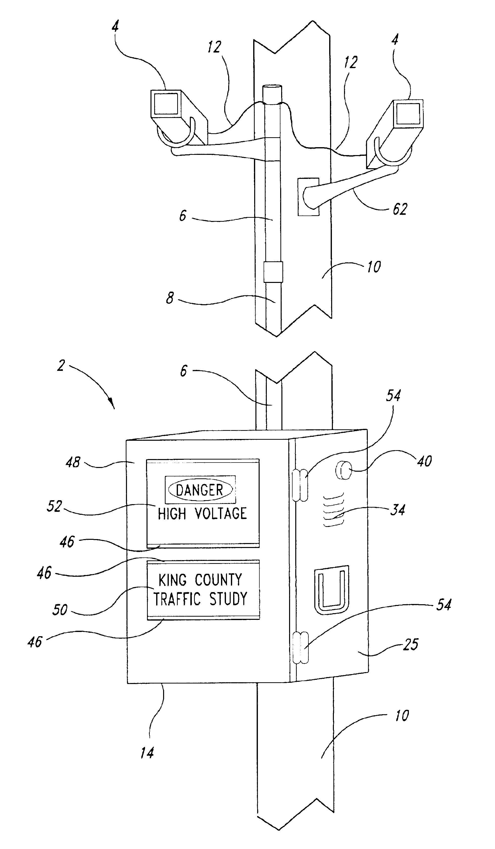
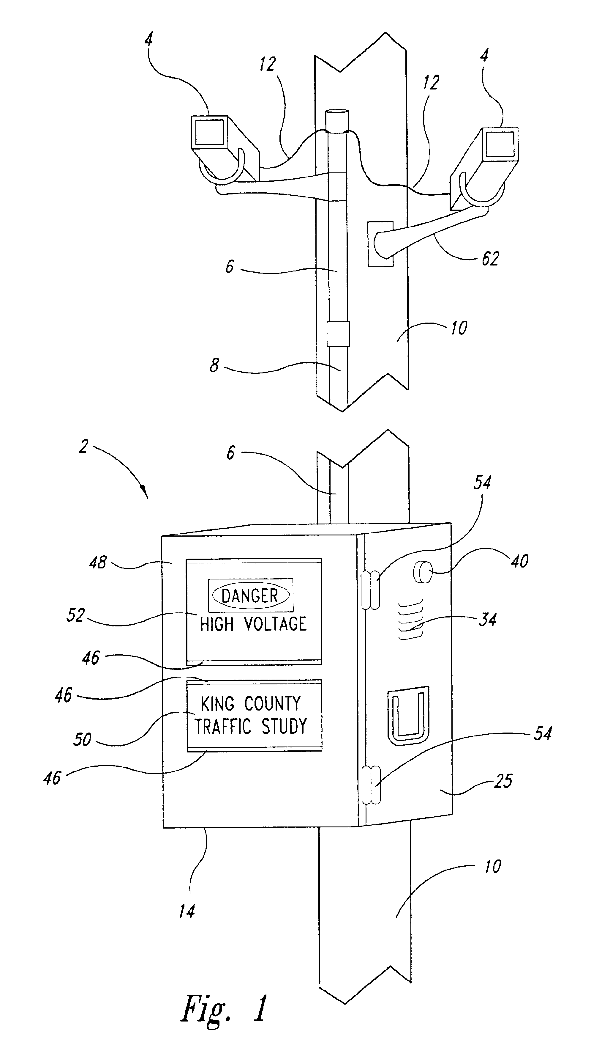
[0011]According to an embodiment of the invention, cables from the plurality of video cameras pass through a conduit extending down from the cameras and into the box to the screen splitter. The top of the conduit is configured to prevent rain from entering the conduit. The conduit may be formed of interlocking segments, which can be stored in a rack located inside a door of the box.
[0012]

Problems solved by technology

First, the expense of paying observers to watch traffic, especially for extended periods, can be significant.
Second, an observer may miss one event while recording another.
Accuracy of recording is also an issue.
The danger also exists that an observer will falsify data, either to achieve a desired result or out of an unwillingness to persevere in the study.
While other methods and devices exist for performing such studies, these also have particular drawbacks.
In addition, such sensors become less effective in multi-lane roadways, and their accuracy can be compromised by multi-axel vehicles, which can be miscounted.
Conventional video systems are expensive to supply and expensive to install and monitor.

Method used


Image

  • Portable traffic surveillance system
  • Portable traffic surveillance system
  • Portable traffic surveillance system

Examples


Embodiment Construction

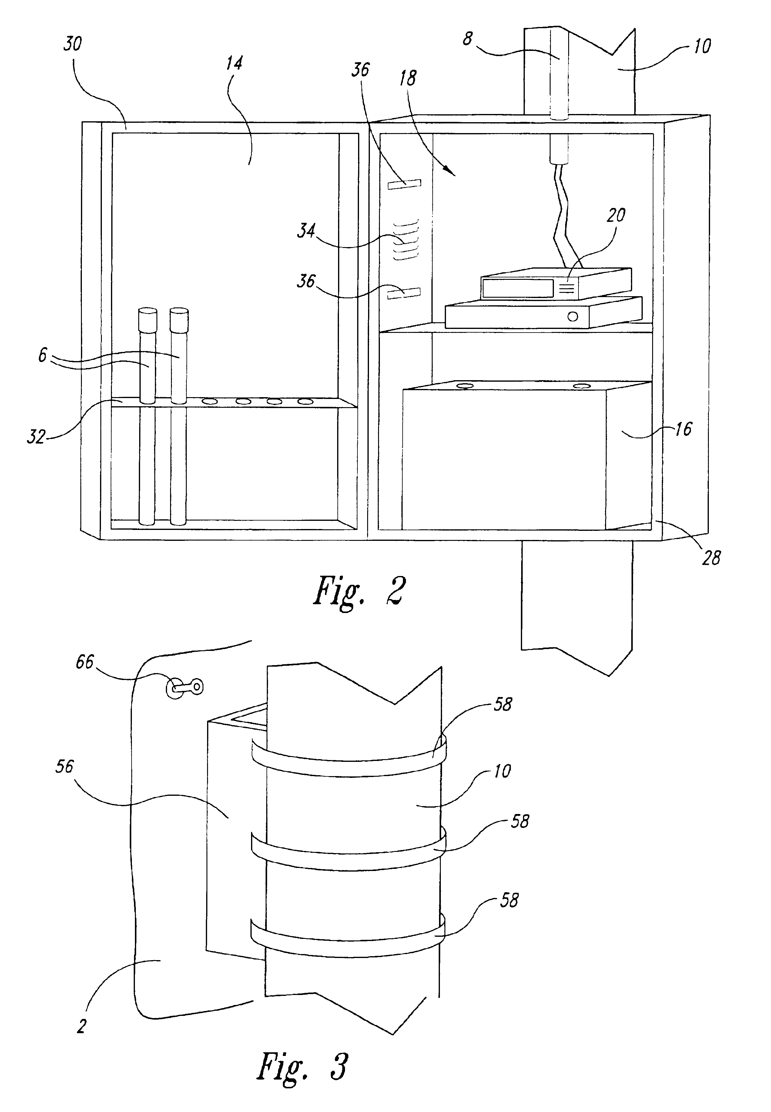
[0028]According to a first embodiment of the invention, a weatherproof box 2 is provided. The box 2 is mounted to a utility pole 10 adjacent to an intersection as shown in FIGS. 1 and 2. A pipe or conduit 8 is attached to the box 2 and rises above the box 2 to a location where a plurality of cameras 4 are attached to the utility pole 10. Video cable 12 from the cameras 4 is routed through the pipe 8 into the box 2. The pipe 8 may be of plastic or metal and is typically segmented to permit storage of the individual segments 6 within the door 14 of the box 2, as shown in FIGS. 2 and 5. The cameras pictured are depicted encased in weatherproof housings which, for the purposes of this description, will be regarded as part of the camera 4.

[0029]As shown in FIGS. 2 and 5, the dimensions of the box 2 are sufficient to accommodate a battery 16 and the appropriate electronics 18 for the system, including a recording device 20. This device 20 may be a video recorder, a computer processor with...


PUM


Abstract

A video system having a plurality of video cameras mounted on a utility pole a distance above the ground, a box mounted on the utility pole below the video cameras, a screen splitter contained inside the box and configured to receive a plurality of video images from the video cameras and to combine the plurality of images into a single video image and a video recorder, also inside the box, configured to record the single video image from the screen splitter. A time and date stamp is recorded on each frame of the single video image. Cables from the plurality of video cameras pass through a conduit extending down from the cameras and into the box to the screen splitter. The top of the conduit is formed of interlocking segments, which can be stored in a rack located inside a door of the box.

Description

CROSS-REFERENCE TO RELATED APPLICATION[0001]This application claims the benefit of U.S. Provisional Patent Application No. 60 / 300,252, filed Jun. 21, 2001, where this provisional application is incorporated herein by reference in its entirety.BACKGROUND OF THE INVENTION[0002]1. Field of the Invention[0003]The present invention relates to the field of video surveillance, and in particular to equipment for use in applications where the need for video surveillance is temporary.[0004]2. Description of the Related Art[0005]As traffic in urban environs increases, the need for improvements to infrastructure also increases. This need is not always matched by available resources for road improvements; thus, a way to prioritize expenditures of resources is needed. One way to do this is to conduct traffic studies that monitor and analyze motor vehicle and pedestrian traffic at locations identified as requiring improvement.[0006]Traffic studies may examine one or more of several components of t...

Claims


Application Information

Patent Timeline
IPC IPC(8): H04N7/18
CPCH04N7/181
Inventor KAYLOR, KENNETHKAYLOR, BRIAN
Owner KAYLOR KENNETH
Learn More