Stereoscopic image display apparatus, display apparatus, divided wave plate filter, plate-shared filter, and filter position adjusting mechanism attached to the display apparatus, aligning apparatus, filter position adjusting method, and filter aligning method

a technology of display apparatus and display apparatus, which is applied in the direction of mountings, instruments, measurement devices, etc., can solve the problems of quality, color representation difficulty, and field of view degradation, and achieve the effect of reliabl

Inactive Publication Date: 2005-11-01
SONY CORP
View PDF12 Cites 42 Cited by
  • Summary
  • Abstract
  • Description
  • Claims
  • Application Information

AI Technical Summary

Benefits of technology

[0032]With the filter aligning apparatus, the filter position detecting means for detecting the position of the plate-shaped filter detects the position of the plate-shaped filter using the alignment mark formed in the filter frame portion, and the display panel position detecting means detects the position of the display panel using the second alignment mark formed in the image display frame portion. In this state, the plate-shaped filter and the display panel are supported by their respective supporting means, and the supporting means can be each controlled by a signal from the control means on the basis of the information of the detected position. It is therefore possible to adjust the positions of the plate-shaped filter and the display panel reliably.

Problems solved by technology

Color separation methods such as the anaglyph methods have many disadvantages in terms of quality, such as difficulty in color representation, degradation in a field of view and the like.
The polarizing glasses methods in general had problems such as necessity of using two projectors However, a method of enabling stereoscopic display with a single direct view type display apparatus has recently been proposed.
This is not easy, and causes the following problems.
A first problem occurs in mounting the divided wave plate filter unit.
While a high-definition panel is available as pixels on a display screen with an increasingly high resolution have become finer, it is extremely difficult to fabricate the corresponding high-definition wave plate filter and fix the divided wave plate filter unit fabricated by the different process with high precision in correspondence with pixels corresponding to the predetermined regions.
In addition, various factors such as vibration during transportation, heat and the like often cause positional displacement.
A glass substrate is generally used for the divided wave plate filter unit to maintain precision of the predetermined regions in many cases because of problems in manufacturing, and hence its own weight, in particular, causes positional displacement.
In addition, positional displacement of the filter may be caused due to various conditions in durability such as deterioration of the fixing agent and the like.
Once the cured resin is displaced, it is extremely difficult to thereafter correct the position, and thus the relatively expensive display panel will be totally wasted.
This presents a problem in that a prefixed position is not necessarily the optimum position at the time of observation. FIG. 2 shows such a state.
Hence, this presents a problem in that a position at which the divided wave plate filter unit is prefixed is not necessarily the optimum position at the time of observation of the divided wave plate filter unit.
Further, the factors as described above cause a problem in that displacement of the divided wave plate filter unit by a few to a few ten % of a pixel (a few ten μm in the above example) is observed as a significant cross talk between images.
This results in a problem in that cross talk between images occurs and hence a good stereoscopic image cannot be displayed.

Method used


Image

  • Stereoscopic image display apparatus, display apparatus, divided wave plate filter, plate-shared filter, and filter position adjusting mechanism attached to the display apparatus, aligning apparatus, filter position adjusting method, and filter aligning method
  • Stereoscopic image display apparatus, display apparatus, divided wave plate filter, plate-shared filter, and filter position adjusting mechanism attached to the display apparatus, aligning apparatus, filter position adjusting method, and filter aligning method
  • Stereoscopic image display apparatus, display apparatus, divided wave plate filter, plate-shared filter, and filter position adjusting mechanism attached to the display apparatus, aligning apparatus, filter position adjusting method, and filter aligning method

Examples


first embodiment

[0074]The stereoscopic image display apparatus 10 has the position adjusting means such as the left adjusting knob 35L and the right adjusting knob 35R and the like. As described above, it is thereby possible to control rotation of the divided wave plate filter unit 12 including fine control of a position of the divided wave plate filter unit 12 in a direction perpendicular to a horizontal direction, that is, a direction in which each divided wave plate of the band shape of the divided wave plate filter unit 12 extends. Thus, optimum stereoscopic display is realized.

[0075]FIG. 4A is an exploded perspective view of assistance in explaining a display structure of the stereoscopic image display apparatus according to the first embodiment. A structure of the liquid crystal panel and a structure of the divided wave plate filter unit are combined with each other to enable stereoscopic display. First, the liquid crystal panel has a structure in which liquid crystal pixel units 32 are disp...

second embodiment

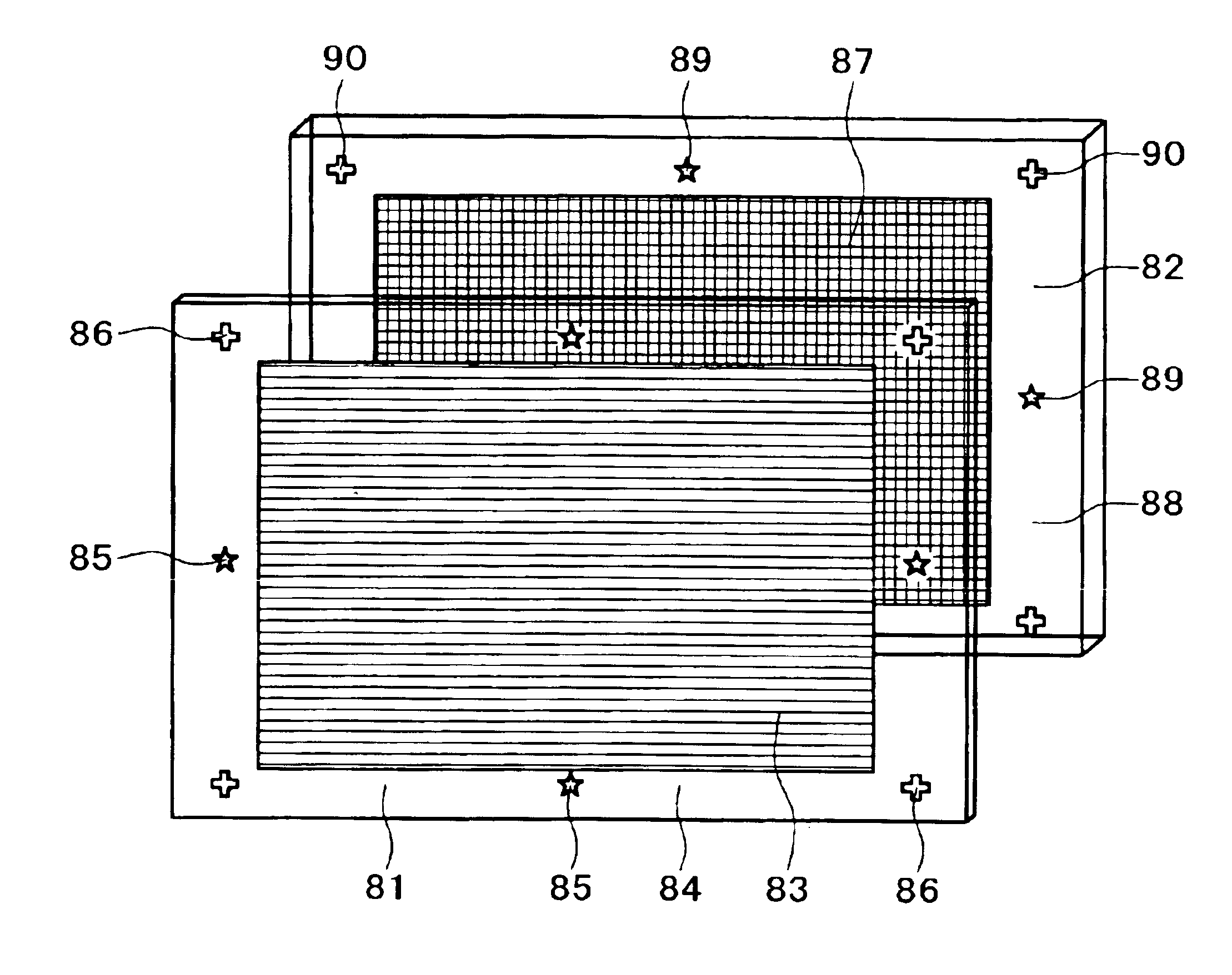
[0119]In the second embodiment, the alignment marks 89 and 90 are set in the same plane shapes of a star and a cross as the alignment marks 85 and 86, respectively, of the filter frame portion 84. In order to pass light patterns in the plane shapes of the star and the cross, the alignment marks 89 and 90 are formed by openings in the shape of the star and the cross in a light shielding film, for example. Since the alignment marks 89 and 90 are in the same shapes as the alignment marks 85 and 86, respectively, of the filter frame portion 84, the position of the marks can be readily detected while utilizing detecting means common between the alignment marks 85 and 86 of the filter frame portion 84 and the alignment marks 89 and 90 of the image display frame portion 88 and the same shape recognition program. It is to be noted that the plane shape of the alignment marks 89 and 90 is not specifically limited as long as the shape is easy to detect. Also, the position of the alignment mark...


PUM


Abstract

A stereoscopic image display apparatus includes: an image display unit 22 for displaying image information corresponding to parallax in a first division and a second division; a divided wave plate filter unit 12 having a frame 41 and disposed adjacent to the first division and the second division of the image display unit, for rotating polarized light of the image information from the first division to a direction different from polarized light of the image information from the second division; and position adjusting means 35R and 35L for acting on the frame of the divided wave plate filter unit and thereby allowing adjustment of a relative position between the image display unit and the divided wave plate filter. Also, a display apparatus includes: a filter unit used in a state of being laid over an image display unit for displaying image information in a first division and a second division; and a filter frame portion disposed integrally around a periphery of the filter unit; wherein the filter unit has a first wave plate in a region corresponding to the first division of the image display unit for rotating polarization direction of the image information from the first division to a direction different from polarization direction of the image information from the second division; and the filter frame portion has an alignment mark formed therein by a second wave plate for rotating polarization direction.

Description

BACKGROUND OF THE INVENTION[0001]The present invention relates to a display apparatus that makes it possible to view an image with parallax information, a plate-shaped filter attached to such a display apparatus, a filter position adjusting mechanism, and a filter position adjusting method, and particularly to a filter position adjusting mechanism and a filter position adjusting method for mounting a divided wave plate filter with high precision for display of an optimum stereoscopic image.[0002]Conventionally, various attempts have been made for technology of representing a three-dimensional image, and methods of display of a three-dimensional image have been studied and put to practical use in many fields such as photography, movies, television and the like. Methods of displaying a three-dimensional image are roughly classified into methods of a glasses type and methods of a no-glasses type. Both types of methods input an image with binocular parallax to a right and a left eye of ...

Claims


Application Information

Patent Timeline
Patent Type & Authority Patents(United States)
IPC IPC(8): G02B27/26G02B27/22G02B7/00G02B30/25H04N13/00H04N13/04
CPCG02B27/26H04N13/0425H04N13/0434H04N13/337H04N13/327G02B30/25G02B27/026G02B27/283G02B30/27
Inventor SATO, SEIJISEKIZAWA, HIDEHIKO
Owner SONY CORP
Why Eureka
Try Eureka