Method for processing video pictures and apparatus for processing video pictures

a technology for video pictures and apparatus, applied in the field of video pictures processing and video pictures processing apparatus, can solve the problems of failure affecting the quality of pictures, failure affecting the human body, and inability to achieve simple design choice of sub-fields, and achieve the effect of efficient false contour effect compensation and easy implementation

Inactive Publication Date: 2005-11-01
INTERDIGITAL MADISON PATENT HLDG
View PDF7 Cites 27 Cited by
  • Summary
  • Abstract
  • Description
  • Claims
  • Application Information

AI Technical Summary

Benefits of technology

[0010]A motion vector is used for re-coding the sub-field code word of a current pixel for false contour effect compensation. This is corresponding to the general idea of another invention of the applicant (see EP-A-0 980 059) according to which the movements in the picture (displacement of the eye focus area) are detected and the right sub-field lighting periods are spread over this displacement in order to ensure that the eye will only perceive the correct information through its movement. Using the motion vector which defines the source of the current pixel has the advantage that a false contour effect compensation can be made reliably even in case of complicated motion in the pictures, like zoom operations or rotations.
[0011]E.g., the appearance of “black holes” in a picture is specifically avoided, if a block spreads out in several different directions since each current block will have only one vector defining one single source (no conflict anymore). Such conflicts occur, if the motion vector is defined in the conventional manner where it points to the place in a following picture to which a current pixel moves.
[0012]The approach of false contour effect compensation based on a motion estimation has the great advantage that it will not add false information in the picture, and in addition, this solution is independent from the picture content. Further advantages are that the inventive method allows a complete correction of the false contour effect when the motion vector is well-known. Therefore, the motion estimator provides best one motion vector for one pixel. For this reason there is no problem if the information of one pixel is spreading in several different directions. Also in the case that different pixels from a previous frame move to the current pixel location there is no conflict, since the motion estimator determines only a single motion vector representing the source of this current pixel.
[0014]Another important advantage is that the picture noise has no impact on the correction quality. The method according to the invention is easy to implement. There is no need of a big memory since it does not need any kind of LUTs like the pulse equalization technique.

Problems solved by technology

On one hand, the plasma display technology gives the possibility of nearly unlimited screen size, also of attractive thickness, but on the other hand, it generates new kinds of artefacts which could damage the picture quality.
In addition, the same problem occurs on static images when observers are shaking their heads and that leads to the conclusion that such a failure depends on the human visual perception and happens on the retina of the eye.
Nevertheless, such a solution can only slightly reduce the false contour effect amplitude but in any cases the effect will still occur and will be perceivable.
Furthermore, sub-field organization is not a simple matter of design choice.
So, optimization of the sub-field organization is only possible in a narrow range and will not eliminate this effect alone.
This technique is a more complex one.
However, the big disadvantage of this technique results from the fact that the equalizing pulses add failures to the picture to compensate for a failure appearing on the eye retina.
Additionally, when the motion is increasing in the picture, there is a need to add more pulses to the picture and that leads to conflicts with the picture contents in case of very fast motion.

Method used


Image

  • Method for processing video pictures and apparatus for processing video pictures
  • Method for processing video pictures and apparatus for processing video pictures
  • Method for processing video pictures and apparatus for processing video pictures

Examples


Embodiment Construction

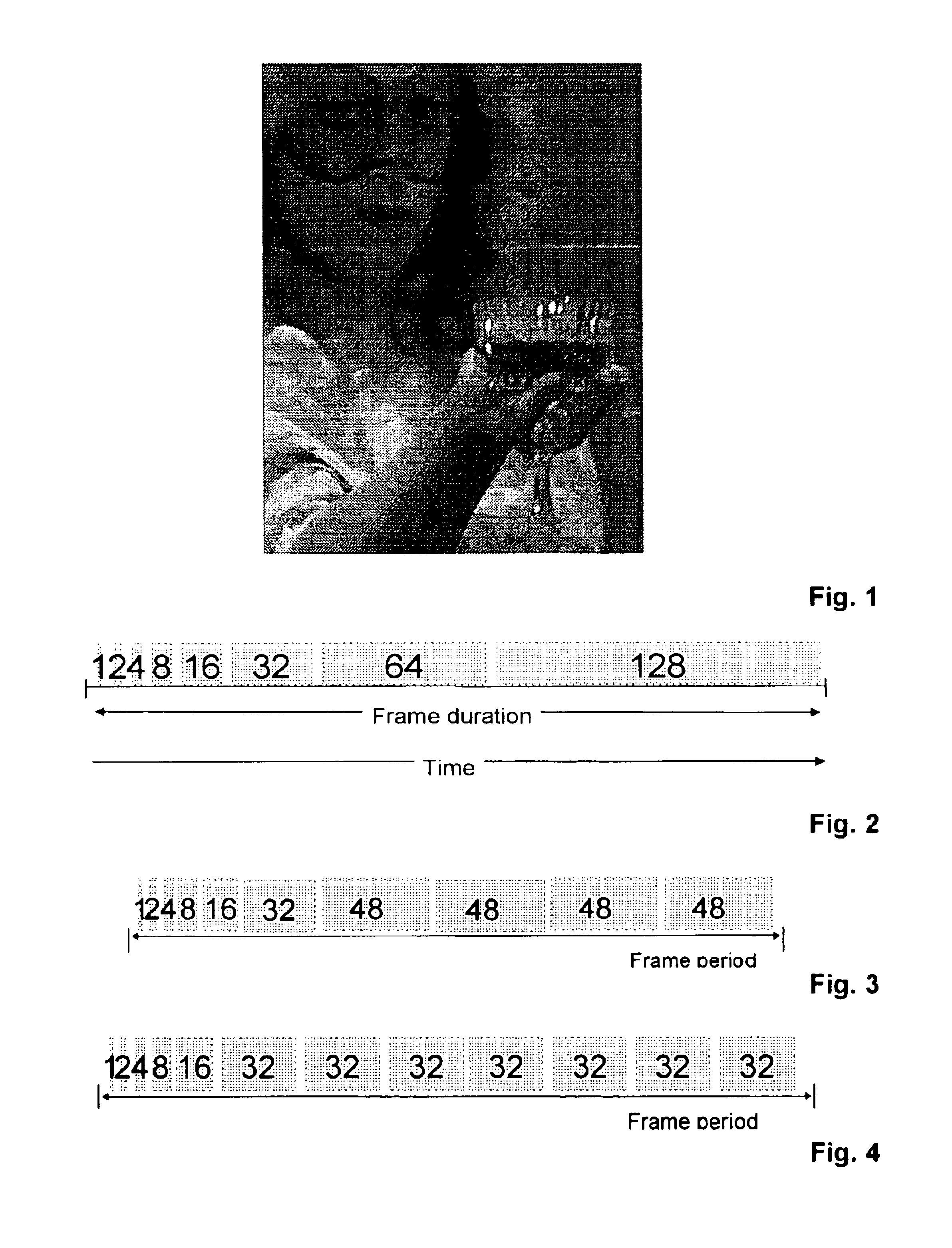
[0033]The artefact due to the false contour effect is shown in FIG. 1. On the arm of the displayed woman are shown two dark lines which, for example, are caused by this false contour effect. Also in the face of the woman such dark lines occur at the right side.

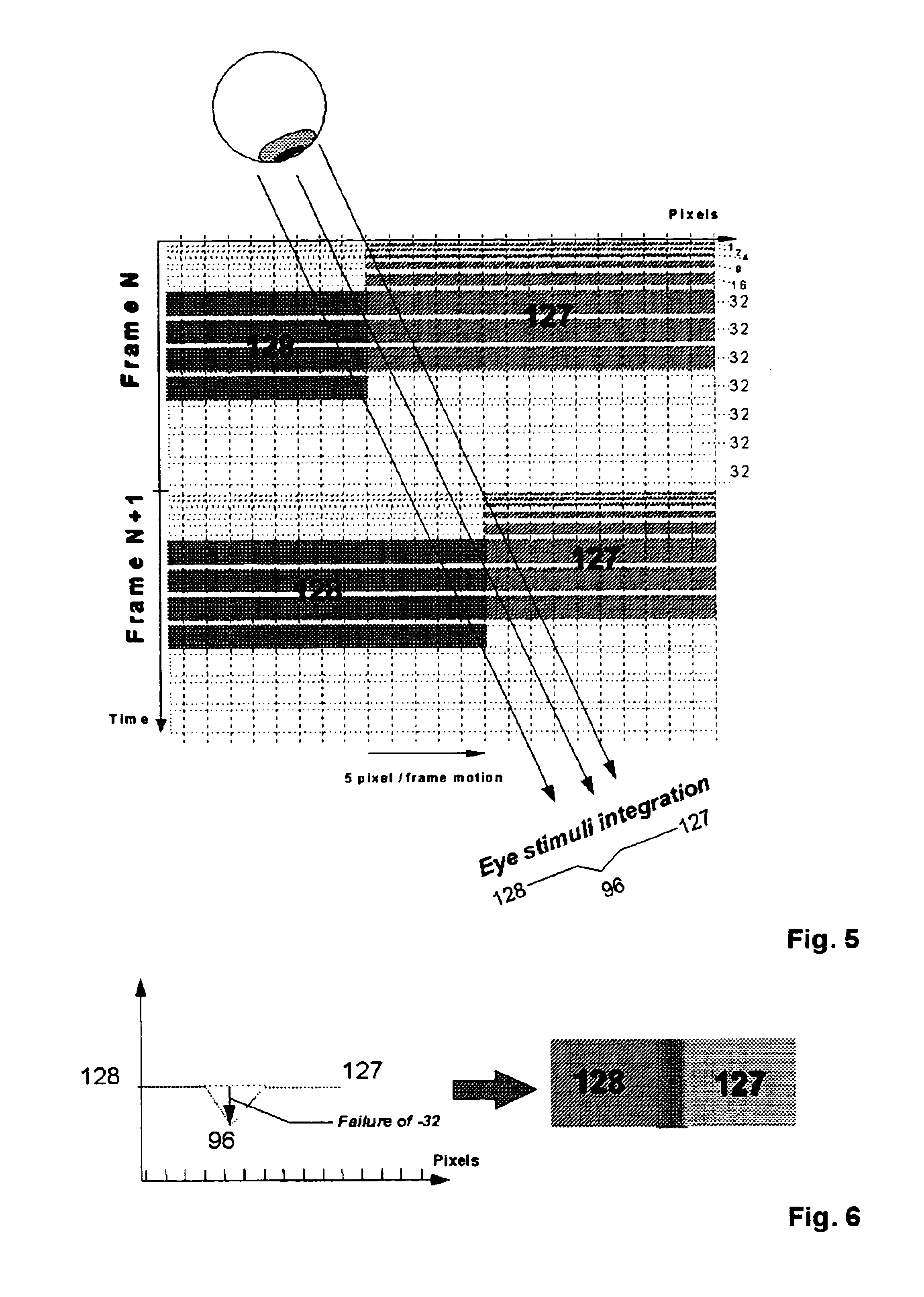
[0034]A plasma display panel utilizes a matrix array of discharge cells which can only be switched ON or OFF. For colour displays, there are three cells required for one pixel according to the three colour components R,G,B. Also unlike a CRT or LCD in which grey levels are expressed by analog control of the light emission, in a PDP the grey levelof each colour component is controlled by modulating the number of light pulses per video frame. This time-modulation will be integrated by the eye over a period corresponding to the eye time response.

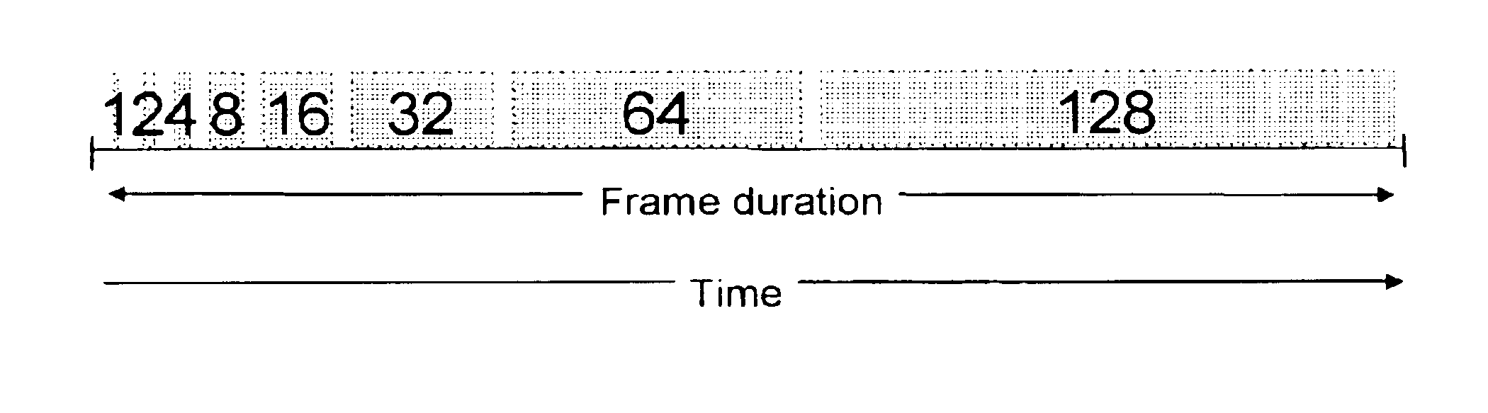
[0035]In the field of digital video processing, all 8-bit (256) luminance levels are represented by a combination of the 8 following bits:[0036]20=1, 21=2, 22=4, 23=8, 24=16, 25=32, 26=64...


PUM

PropertyMeasurementUnit
drag coordinatesaaaaaaaaaa
gravityaaaaaaaaaa
colouraaaaaaaaaa

Abstract

With the new plasma display panel technology new kinds of artifacts can occur in video pictures. These artifacts are commonly described as dynamic false contour effect, since they correspond to disturbances of grey levels and colors in the form of an apparition of colored edges in the picture when the observation point on the PDP screen moves. According to the invention such an artifact is compensated by analyzing the motion in the pictures assigning to each block of a picture a corresponding motion vector and performing a re-coding step in which a sub-field code word entry of a current pixel are calculated. For this purpose the motion vector is defined to point from a pixel in a previous picture to a pixel in the current picture. The sub-field code word entries for a current pixel (P8) are determined by dragging sub-field entries of the pixels lying on the motion vector trajectory. In this way for each pixel there is an exact calculation of the sub-field code word of a pixel also for complex moving trajectories like zoom and rotation.

Description

[0001]The invention relates to a method and an apparatus for processing video pictures, especially for a false contour effect compensation.[0002]More specifically the invention is closely related to a kind of video processing for improving the picture quality of pictures which are displayed on matrix displays like plasma display panels (PDP), LCOS or display devices with digital micro mirror arrays (DMD).BACKGROUND OF THE INVENTION[0003]Although plasma display panels are known for many years, plasma displays are encountering a growing interest from TV manufacturers. Indeed, this technology now makes it possible to achieve flat color panels of large size and with limited depths without any viewing angle constraints. The size of the displays may be much larger than the classical CRT picture tubes would have ever been allowed.[0004]Referring to the latest generation of European TV sets, a lot of work has been made to improve its picture quality. Consequently, there is a strong demand, ...

Claims


Application Information

Patent Timeline
Patent Type & Authority Patents(United States)
IPC IPC(8): G06T5/20G06T7/20G02F1/133G09G3/20G09G3/28G09G3/34G09G3/36H04N5/208H04N5/66
CPCG06T5/20G09G3/2022G09G3/2029G09G3/2033G09G3/28G09G3/2803G09G2320/0261G09G2320/0266G09G2320/106G09G3/288H04N5/208
Inventor WEITBRUCH, SEBASTIENCORREA, CARLOSZWING, RAINER
Owner INTERDIGITAL MADISON PATENT HLDG
Why Eureka
Try Eureka