Interface member wiring design support apparatus, wiring design method, wiring design support method, and computer-readable storage medium

a technology of wiring design and support apparatus, which is applied in the direction of computation using non-denominational number representation, instruments, transportation and packaging, etc., can solve the problems of not considering the strength of semi-fixed support members (clips) for fixing the wire harness, the difficulty of directly manufacturing an actual product in accordance with the generated shape, and the difficulty of grasping, for example, how much strength is necessary or appropriate for fixing the wire

Active Publication Date: 2005-11-01
MAZDA MOTOR CORP
View PDF5 Cites 11 Cited by
  • Summary
  • Abstract
  • Description
  • Claims
  • Application Information

AI Technical Summary

Benefits of technology

[0012]It is an object of the present invention to provide an interface member wiring design support apparatus, wiring design method, wiring design support method, and computer-readable storage device, which calculate a more practical shape with simple set items and inform the calculated shape.

Problems solved by technology

If, therefore, such a simulation is applied to, for example, the design of wire harness wiring, since no consideration is given to the weight and hardness (rigidity) of the wire harness and dynamic factors such as force produced at fixed positions such as connectors due to these factors, it is often difficult (impractical) to directly manufacture an actual product in accordance with the generated shape.
In the prior art described above, however, no consideration is given to semifixed support members (clips) for fixing the wire harness, branch portions provided for the same wire harness, forces that are produced at the respective fixed points as the wire harness bends, and the like.
In addition, in the automatically calculated shape of a wire harness, the forces acting on connectors and the like on the two end portions of the wire harness are not clarified, it is difficult to grasp, for example, how much strength is necessary or appropriate in fixing the wire harness.

Method used


Image

  • Interface member wiring design support apparatus, wiring design method, wiring design support method, and computer-readable storage medium
  • Interface member wiring design support apparatus, wiring design method, wiring design support method, and computer-readable storage medium
  • Interface member wiring design support apparatus, wiring design method, wiring design support method, and computer-readable storage medium

Examples


Embodiment Construction

[0045]An interface member wiring design support apparatus and wiring design method according to the present invention will be described in detail below with reference to the accompanying drawings as an embodiment in which the present invention is applied to the wiring design of a wire harness formed by binding a plurality of electric wires into a bundle and attaching a predetermined connector to each end portion of the bundle.

[0046]Note, in the present invention, the interface member (in other words, a line member or a line object) includes not only the wire harness but also various kinds of cables such as an optical cable and electrical cable, and pipe for carrying fluid.

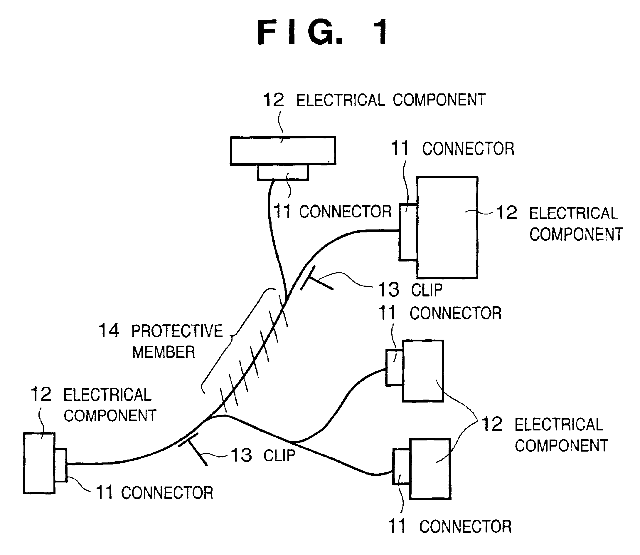
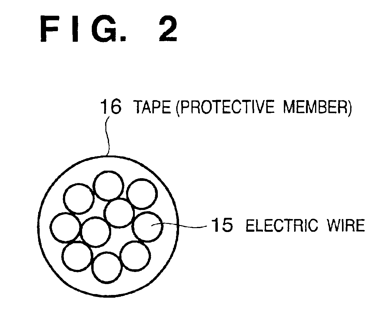
[0047]FIG. 1 is a view showing an example of the overall shape of a wire harness as a design target in this embodiment. FIG. 2 is a view showing an example of the sectional shape of the wire harness in FIG. 1.

[0048]The wire harness shown in FIG. 1 has connectors 11 at the respective end portions, which are connecte...


PUM

PropertyMeasurementUnit
modulus of deformationaaaaaaaaaa
flexural rigidityaaaaaaaaaa
diameteraaaaaaaaaa

Abstract

Flexural rigidity E of a target wire harness (to be referred to as a WH hereinafter) is calculated by a predetermined bi-quadratic function associated with a curvature ρ on the basis of a diameter φ of the WH, and the wiring shape of the WH which satisfy fixing positions is calculated on the basis of torsional rigidity C and the weight per unit length which are supplied from a storage device in accordance with the diameter φ of the target WH (S4-S5). The bi-quadratic function is set such that the calculated flexural rigidity E decreases as the curvature ρ of the WH increases.

Description

FIELD OF THE INVENTION[0001]The present invention relates to an interface member wiring design support apparatus and wiring design method and, more particularly, to a support apparatus and wiring design method for supporting optimal wiring design for various types of wire harnesses at the site of design of an automobile or the like.BACKGROUND OF THE INVENTION[0002]Interface members for connecting a given electrical component to another electrical component or a given package to another package are used in a vehicle such as an automobile or an electronic device such as a household electrical appliance.[0003]As a typical interface member, a so-called wire harness is available, which is formed by binding a plurality of electric wires or communication lines into a bundle by using a protective member such as a tape as needed and attaching predetermined connectors to the two end portions of the bundle. Wire harnesses differ in the numbers of electric wires and the thickness of each electr...

Claims


Application Information

Patent Timeline
Patent Type & Authority Patents(United States)
IPC IPC(8): B60R16/02G06F17/50H01R43/28H01B13/012
CPCB60R16/0207B60R16/0215G06F17/509G06F17/5095H01R43/28G06F2217/36G06F30/15G06F30/18G06F2113/16
Inventor KODAMA, NOBUHIROYOSHIYUKI, TAKASHIHIRANO, SEIICHIFUKUSHIMA, TOMOHIRO
Owner MAZDA MOTOR CORP
Why Eureka
Try Eureka