

Honeycomb structure
a honeycomb and structure technology, applied in the field of honeycomb structure, can solve the problems of higher degree of production difficulty, deterioration of structure strength of honeycomb structure, cell deformation shape change, etc., and achieve the effect of not easily deteriorating structure strength and not easily changing cell shap
- Summary
- Abstract
- Description
- Claims
- Application Information
AI Technical Summary
Benefits of technology
Problems solved by technology
Method used
Image

Examples
example 1
[0072]As cordierite forming raw materials, alumina, aluminum hydroxide, kaolin, talc and silica were used. To 100 parts by mass of the cordierite forming raw materials, 5 parts by mass of a pore former, 85 parts by mass of water (a dispersion medium), 8 parts by mass of water-absorbing hydroxypropyl methylcellulose (an organic binder) and 3 parts by mass of a surfactant were added. Afterward, mixing was performed, and kneading was further performed, to obtain a kneaded material.
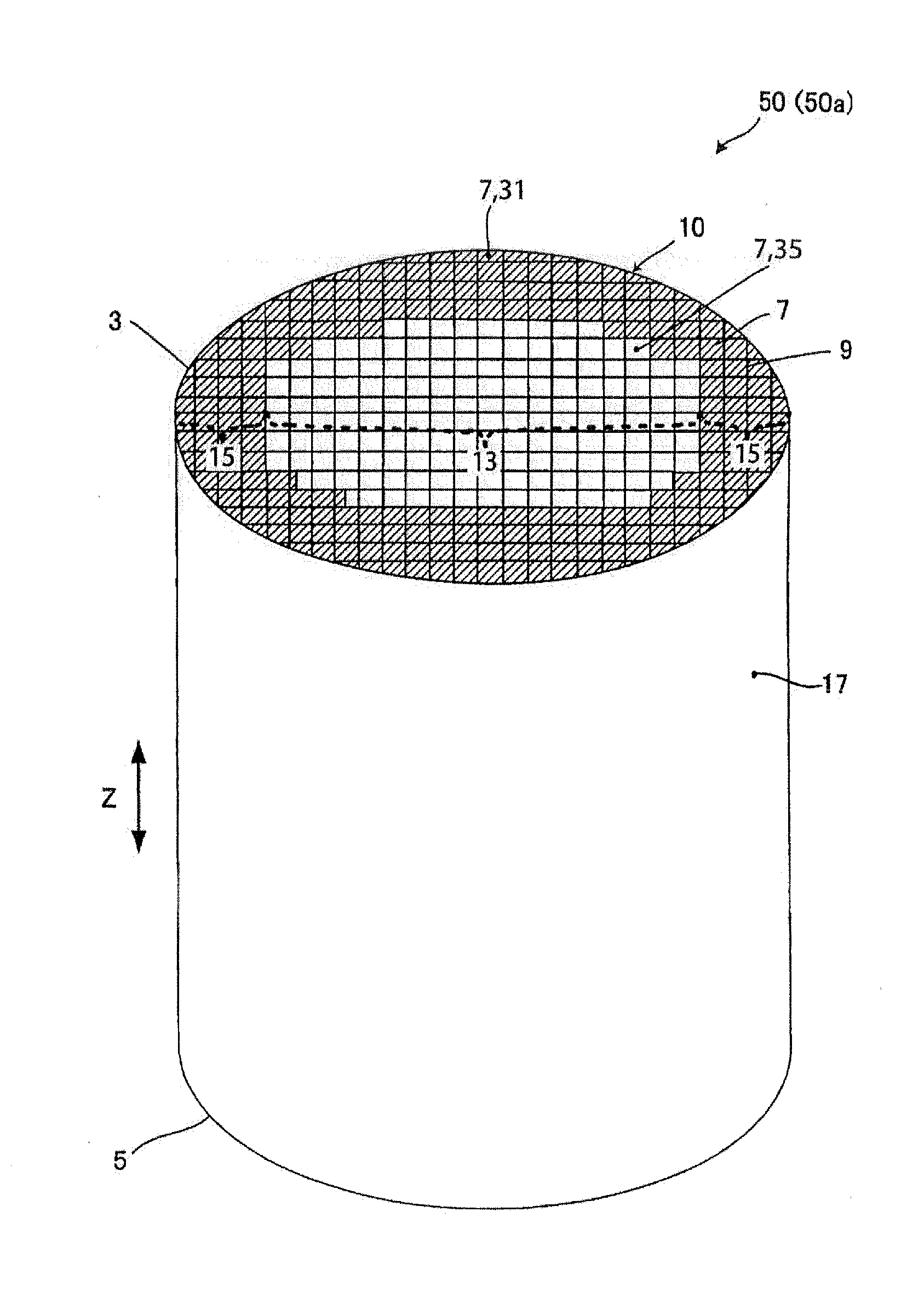
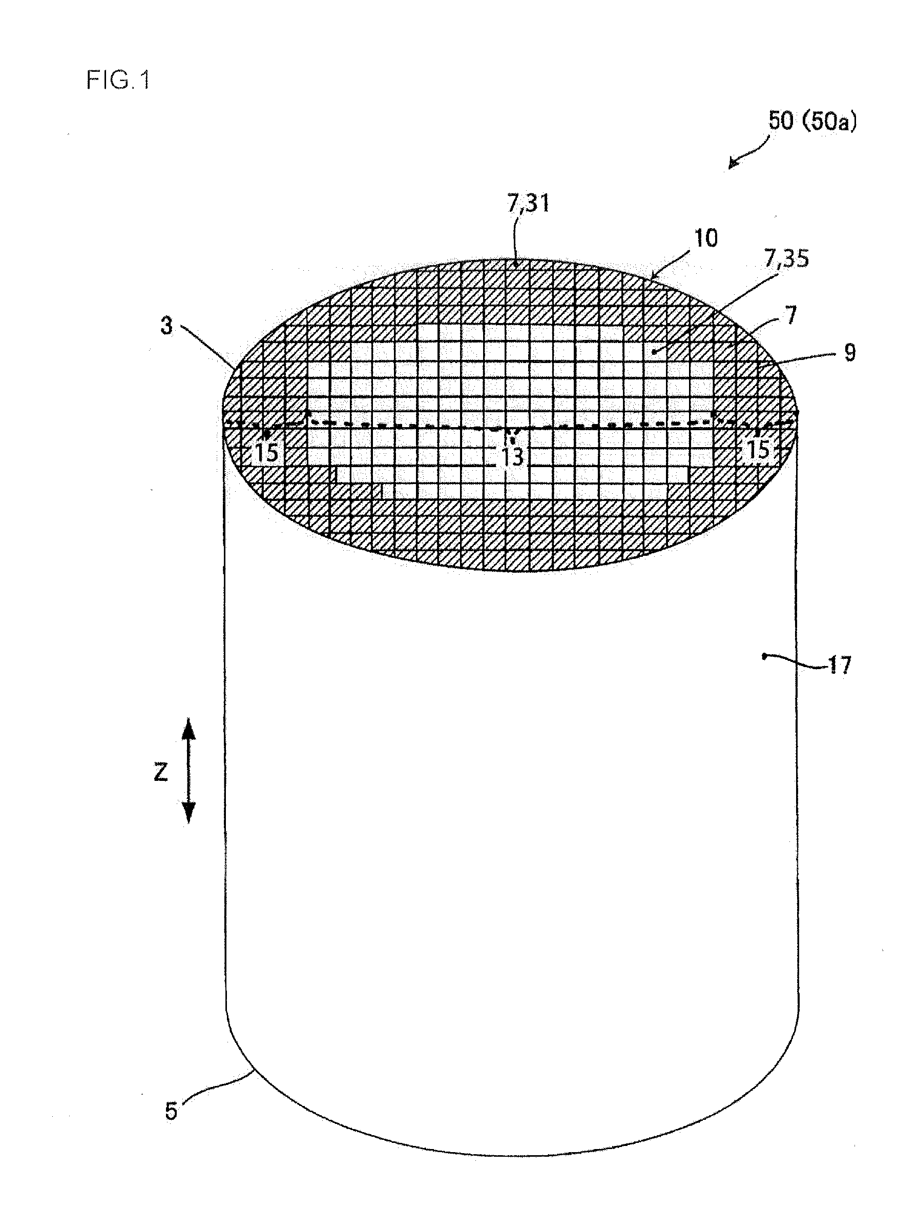
[0073]Next, the kneaded material was extruded by using a predetermined die to obtain a honeycomb formed body. In the honeycomb formed body, quadrangular cells were formed in a cross section perpendicular to an extending direction of the cells, and the whole shape was a columnar shape. Then, the obtained honeycomb formed body was dried by a microwave drier. Afterward, the body was further dried completely by a hot air drier. Next, both end surfaces of the dried honeycomb formed body were cut, to regulate the b...
PUM
| Property | Measurement | Unit |
|---|---|---|
| porosity | aaaaa | aaaaa |
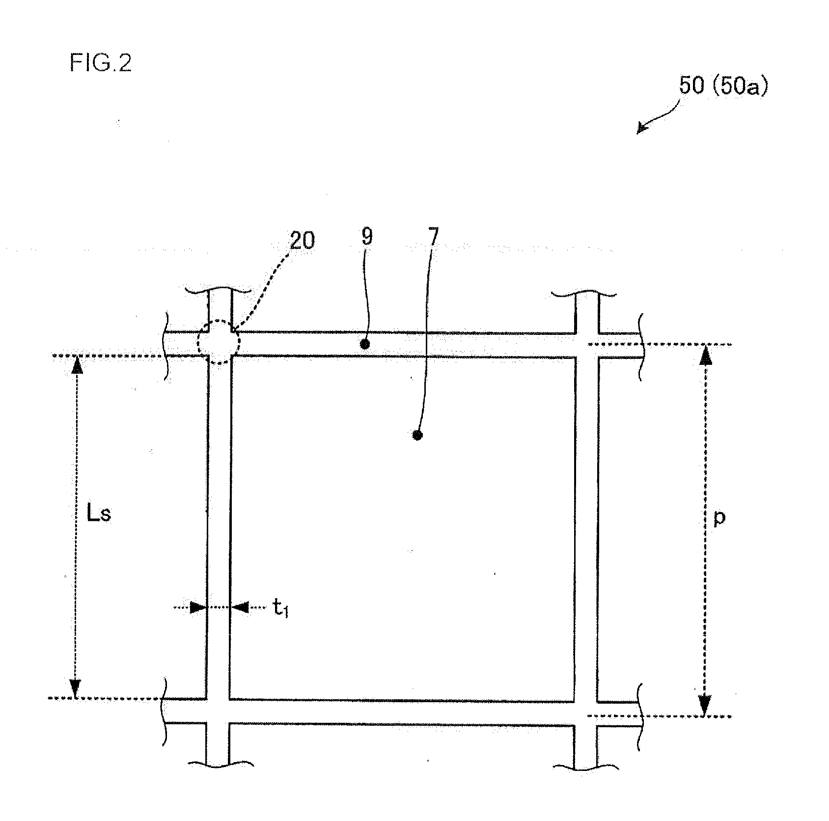
| thickness t1 | aaaaa | aaaaa |
| porosity | aaaaa | aaaaa |
Abstract
Description
Claims
Application Information