
Automation system for controlling and monitoring devices and sensors

a technology of automatic monitoring and monitoring devices, applied in the direction of static/dynamic balance measurement, data switching networks, instruments, etc., can solve the problems of limited current power line networking, inability to control appliances, lamps, other power line devices in the home, and inability to control phone line devices

Inactive Publication Date: 2005-11-01
MICROSOFT TECH LICENSING LLC
View PDF28 Cites 150 Cited by
  • Summary
  • Abstract
  • Description
  • Claims
  • Application Information

AI Technical Summary

Benefits of technology

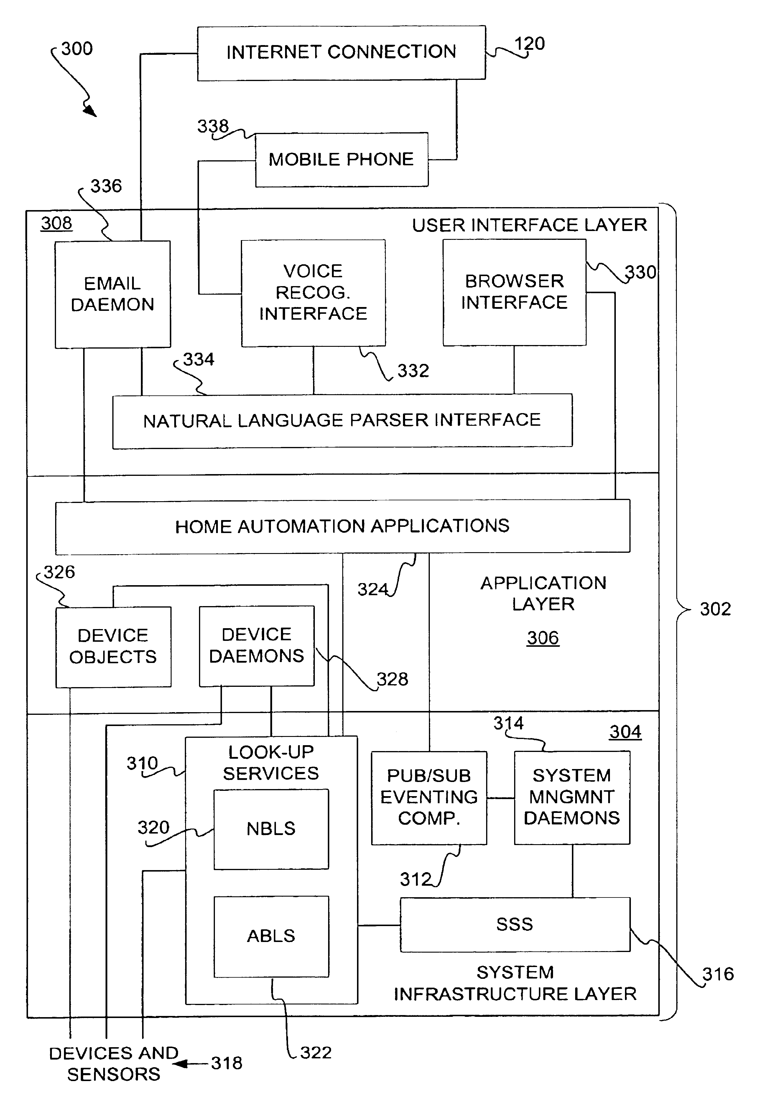
[0009]The invention provides an architecture for controlling and monitoring these devices and sensors in an intelligent, reliable, and robust manner. With respect to intelligence, for example, the architecture includes look-up services that maintain a database of all available devices in a user-friendly manner. Rather than remembering a lamp by an archaic address, a homeowner may simply identify the lamp as “the lamp plugged into the eastern wall of the bedroom.” Other aspects of the architecture provide for sophisticated and complex automation applications to intelligently control and monitor devices and sensors.
[0011]With respect to robustness, the architecture can have built-in redundancy in the number of computers over which the architecture is implemented, as well as in the number of instances of certain types of important system management daemons. Redundant daemon instances utilize a weak-leader approach to determine which among them is the current leader instance that should respond to inquiries made to the daemon. If the leader daemon instance fails, one of the redundant daemon instances becomes the new leader instance, so that the system does not go offline.

Problems solved by technology

While phone line networking allows homeowners to create small local-area networks (LAN's) within their homes for the purposes of connecting computers and computer peripherals, it has limitations.
Significantly, phone line networking typically does not allow homeowners to control appliances, lamps, and other power line devices within their homes.
Current power line networking, such as X10 networking, is limited.
The framework generally does not allow for sophisticated and complex device control applications.
While automation systems employing existing X10 technology can be implemented using computers, more typically the systems are implemented with relatively less intelligent control centers that only govern a limited number of power line devices, in a limited manner.
When computers are used, the resulting systems are still far from ideal.
They may be difficult to use, and may not be reliable or robust against equipment failures and crashes.

Method used


Image

  • Automation system for controlling and monitoring devices and sensors
  • Automation system for controlling and monitoring devices and sensors
  • Automation system for controlling and monitoring devices and sensors

Examples


Embodiment Construction

[0027]In the following detailed description of exemplary embodiments of the invention, reference is made to the accompanying drawings that form a part hereof, and in which is shown by way of illustration specific exemplary embodiments in which the invention may be practiced. These embodiments are described in sufficient detail to enable those skilled in the art to practice the invention. Other embodiments may be utilized, and logical, mechanical, electrical, and other changes may be made without departing from the spirit or scope of the present invention. The following detailed description is, therefore, not to be taken in a limiting sense, and the scope of the present invention is defined only by the appended claims.

Hardware Architecture

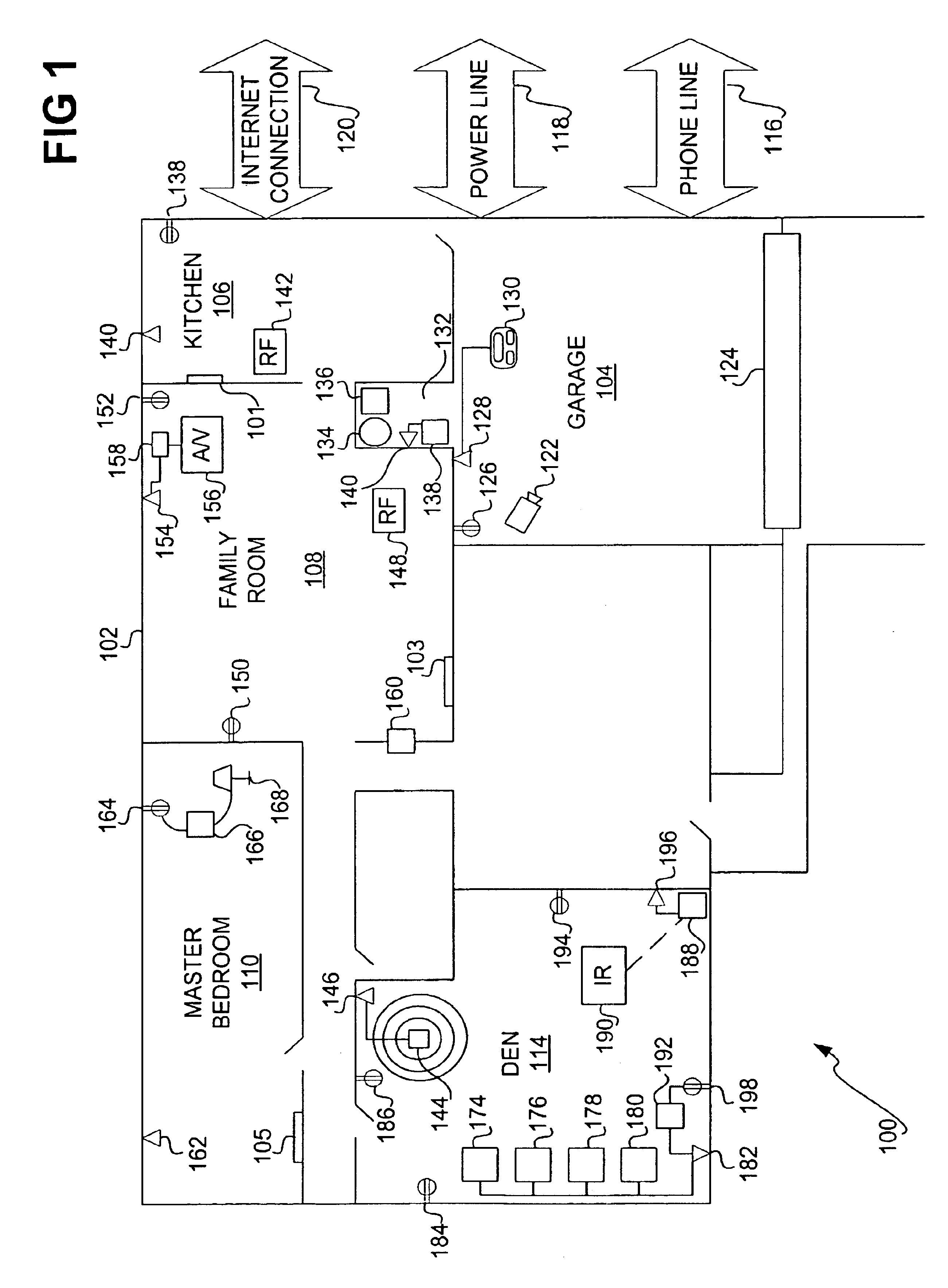
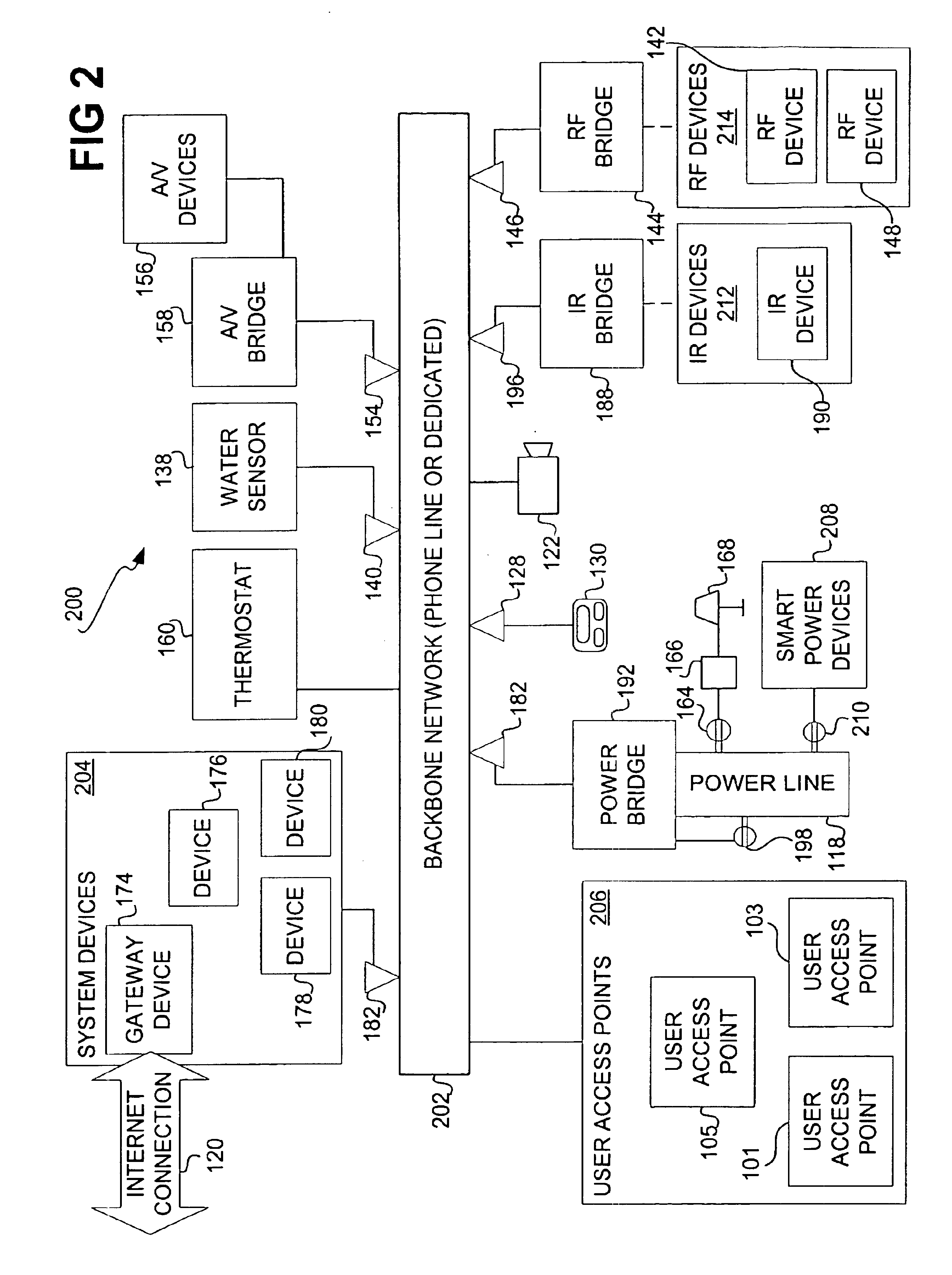
[0028]FIG. 1 shows a pictorial diagram 100 of an example house 102 in which an automation system of the invention can be implemented. The house 102 includes a garage 104, a kitchen 106, a family room 108, a master bedroom 110, and a den 114, among o...


PUM


Abstract

An architecture for an automation system is disclosed that includes look-up services, a soft-state store, and a publication / subscription eventing component. The look-up services maintain a database of a number of devices to be controlled and monitored, and a database of a number of device objects corresponding to the devices. The services can be divided into attribute-based and name-based services. The soft-state store manages variables regarding the devices and the device objects, including heartbeats. The eventing component enables subscriptions to events related to changes in the variables. The architecture can include management daemons, such as a monitoring daemon that detects problems with power line devices.

Description

RELATED APPLICATIONS[0001]This patent application claims priority to and the benefit of the previously filed provisional patent applications “Home Networking,” filed on Aug. 17, 1999, and assigned Ser. No. 60 / 149,390, and “Home Networking System,” filed on Feb. 24, 2000, and assigned Ser. No. 60 / 184,631.FIELD OF THE INVENTION[0002]This invention relates generally to controlling and monitoring devices and sensors, such as devices and sensors that connect to the power line, and more particularly to an automation system for controlling and monitoring devices and sensors.BACKGROUND OF THE INVENTION[0003]Home networking and automation have become more popular. With the number and complexity of audio / video equipment increasing, some homeowners are interested in operating their equipment more easily. Other homeowners are more concerned about the security and safety of their homes. These homeowners may want to remotely monitor their homes, remotely control appliances and other power line de...

Claims


Application Information

Patent Timeline
Patent Type & Authority Patents(United States)
IPC IPC(8): G06F15/173G06F15/16H04L12/28H04L29/08
CPCH04L12/2803H04L12/2809H04L12/282H04L67/025H04L2012/2843H04L2012/2849H04L2012/285Y10S707/99945Y10S707/99948
Inventor WANG, YI-MINRUSSELL, WILF G.XU, JUNARORA, ANISH K.BAHL, PARAMVIR
Owner MICROSOFT TECH LICENSING LLC
Learn More