Disc carrier having a clamping device for use in an optical disc drive

a technology of optical disc drives and clamping devices, which is applied in the direction of magnetic recording, data recording, instruments, etc., can solve the problems of complicated assembly procedures, and achieve the effect of improving rotating stability

Inactive Publication Date: 2005-11-01
SUNONWEALTH ELECTRIC MACHINE IND
View PDF3 Cites 12 Cited by
  • Summary
  • Abstract
  • Description
  • Claims
  • Application Information

AI Technical Summary

Benefits of technology

[0007]An object of the present invention is to provide a disc ca

Problems solved by technology

However, it was found that the engaging member 11a was apt to incline relative to the disc carrier 10 and thus caused imbalance.
Further, the assembling p

Method used


Image

  • Disc carrier having a clamping device for use in an optical disc drive
  • Disc carrier having a clamping device for use in an optical disc drive
  • Disc carrier having a clamping device for use in an optical disc drive

Examples


Embodiment Construction

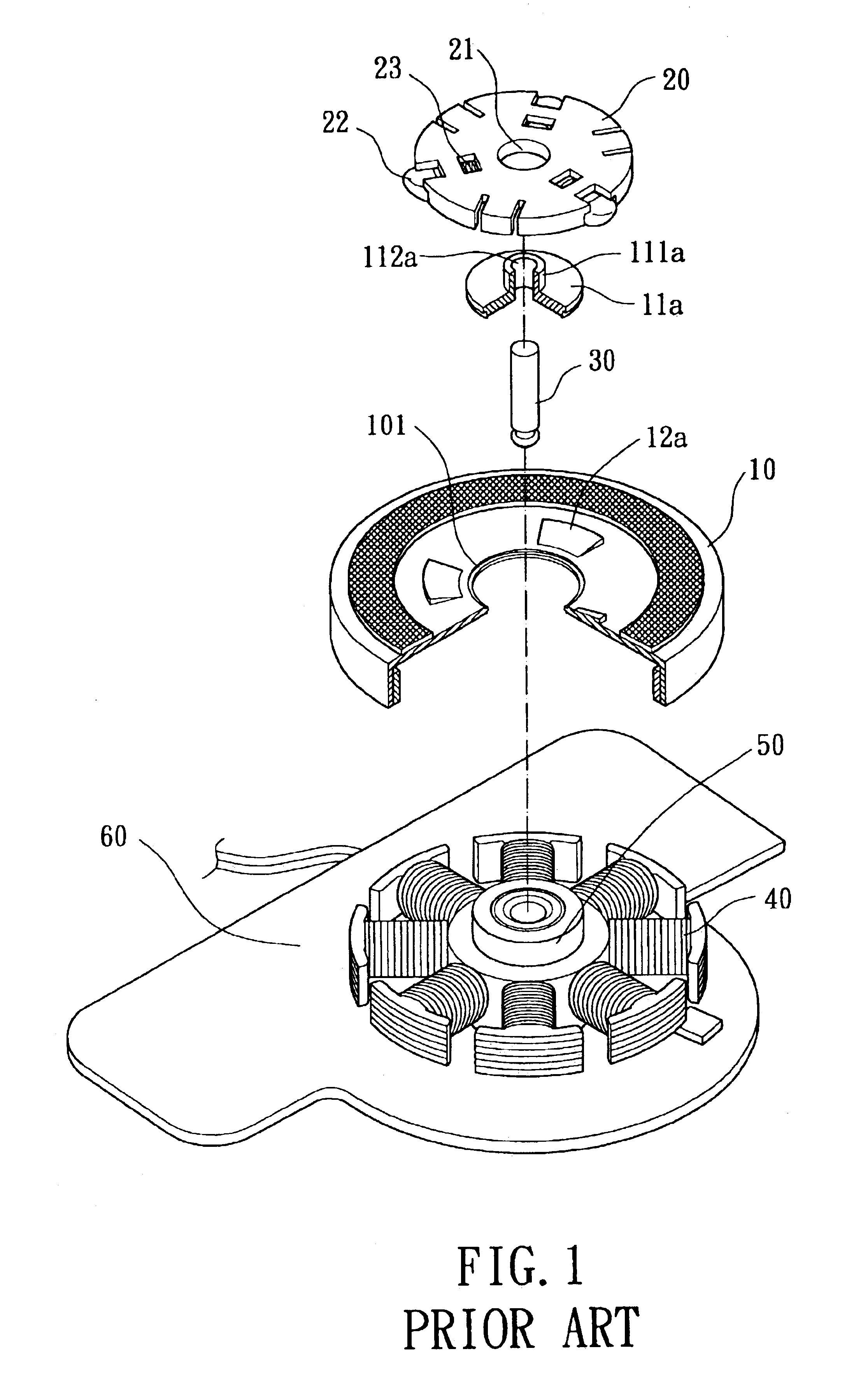
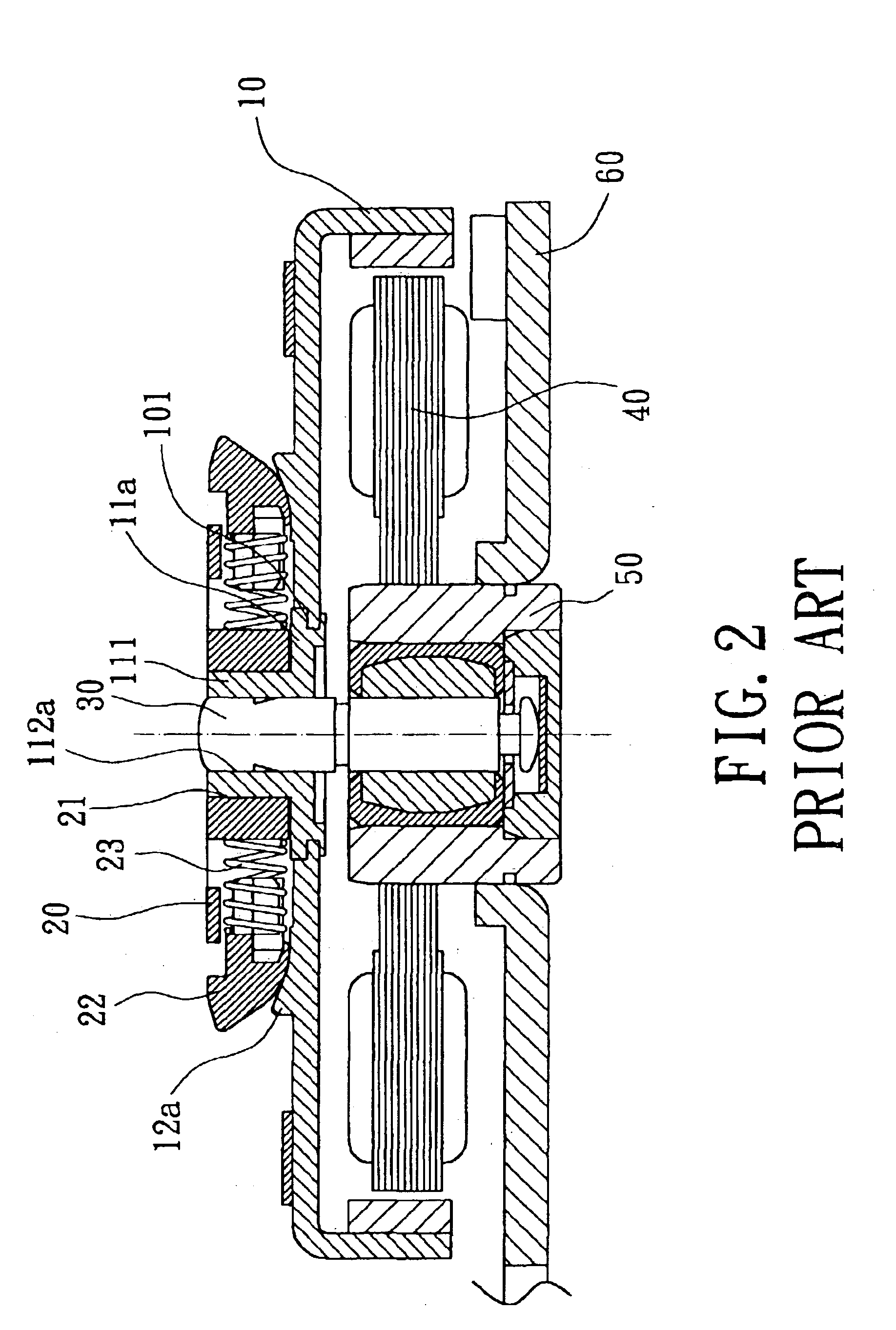
[0018]A preferred embodiment of the present invention is now to be described hereinafter in detail, in which the same reference numerals are used in the preferred embodiments for the same parts as those in the prior art to avoid redundant description.

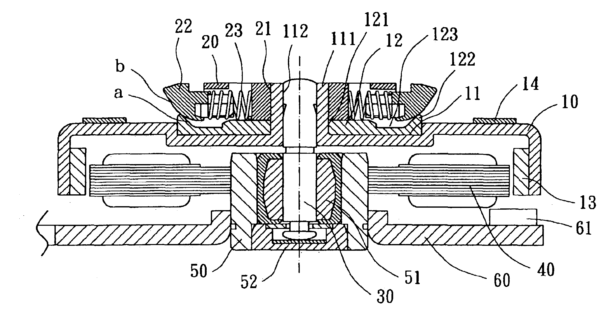
[0019]Referring to FIGS. 3 and 4, a disc carrier 10 in accordance with the present invention is generally a rotor of a spindle motor and includes a recession 11 in a top side thereof, an axial tube 111, and a support member 12. The recession 11 is integrally formed on the disc carrier 10 by means of punching, casting, etc. The axial tube 111 projects from a central portion of a bottom wall 110 of the recession 11 and extends along a longitudinal axis to a level the same as that of the conventional design. Thus, the axial tube 111 is longer than the axial tube 11a in FIGS. 1 and 2, as the axial tube 111 extends from a point lower than the axial tube 11a of the conventional design. The support member 12 is made of plastic or metal and fix...


PUM


Abstract

A disc carrier for an optical disc drive includes a recession integrally formed thereon and an axial tube projecting from a central portion of a bottom wall of the recession. A shaft extends through the axial tube. An engaging length between the axial tube and the shaft is increased to improve rotating stability of the disc carrier. A support member is fixed in the recession and includes a peripheral support edge along a periphery thereof. The support member is in contact with and thus supports plural clamping members of a clamping device.

Description

BACKGROUND OF THE INVENTION[0001]1. Field of the Invention[0002]The present invention relates to a disc carrier for an optical disc drive. In particular, the present invention relates to a disc carrier for an optical disc drive with improved rotating stability.[0003]2. Description of Related Art[0004]FIGS. 1 and 2 of the drawings illustrate an optical disc drive with a conventional disc carrier. The optical disc drive comprises a spindle motor including a disc carrier 10, a clamping device 20, a shaft 30, a stator assembly 40, a bearing seat 50, and a base 60. The disc carrier 10 is a rotor of the spindle motor and includes a hole 101 to which an engaging member 11a is securely mounted. The engaging member 11a includes an axial tube 111a with an axial hole 112a. Plural support blocks 12a are formed, by means of punching, on a top face of the disc carrier 10 for supporting plural clamping members 22 of the clamping device 20. The clamping device 20 includes a central hole 21, plural ...

Claims


Application Information

Patent Timeline
IPC IPC(8): G11B17/02G11B17/038G11B17/028
CPCG11B17/038G11B17/0282
Inventor HORNG, ALEXHONG, YIN-RONG
Owner SUNONWEALTH ELECTRIC MACHINE IND
Why Eureka
Try Eureka