Method of improving a signal in a sequence of images acquired with a digital color video camera

a color video camera and image sequence technology, applied in the field of improving the signal in the image sequence acquired with a digital color video camera, can solve the problems of reducing the real-time capability of digital image processing, and limiting the complexity of the novel method. , to achieve the effect of avoiding delay and limiting the complexity of the novel method

Inactive Publication Date: 2005-11-08
KAPPA OPTO ELECTRONICS
View PDF18 Cites 6 Cited by
  • Summary
  • Abstract
  • Description
  • Claims
  • Application Information

AI Technical Summary

Benefits of technology

[0017]The novel method performs dynamic subtraction of offset values and multiplication of gain values, the offset values and the gain values being continuously calculated. The calculation of the new offset value and of the new gain value is realized in a known way using the minimal brightness value and maximum brightness value in an image or in a predetermined image sector or section. However, the novel method substantially differs from the known image processing software by taking into account not only the minimum brightness value and the maximum brightness value of a single image or a image section, but also at least a further set of previously calculated brightness values to determine a specific brightness value. In this way, “jumping” of the offset values and of the gain values in the sense of brightness flickering is prevented. These novel steps also mean that the offset value and the gain value being used to modify a certain image are at least in part calculated using image data from previous images. Furthermore, to limit complexity of the novel method and to increase its real-time capability without special expenditure in hardware, it is possible to limit evaluation of the digital video signal and correspondingly the continuous calculation of the offset value and the gain value to a part of the whole image sequence. This means that not every image of the image sequence is evaluated and, accordingly, the offset value and the gain value does not change with each new image of the image sequence. Moreover, the single images of the image sequence would have to be delayed to modify them with the immediately corresponding offset and gain value. These have to be calculated first from the images. With the novel method, it is preferred to avoid the delay. The novel method uses the last calculated offset value and the last calculated gain value for the modification of the current image, even if these were entirely taken from the previous images. It turns out that the offset values and the gain

Problems solved by technology

In contrast, the brightness resolution of the human eye is very limited.
A brightness resolution of more than 7 bits (which corresponds to 127 levels of brightness) does not produce a visible quality improvement when displaying images.
This known digital image processing existing in software does not—wi

Method used


Image

  • Method of improving a signal in a sequence of images acquired with a digital color video camera
  • Method of improving a signal in a sequence of images acquired with a digital color video camera

Examples


Embodiment Construction

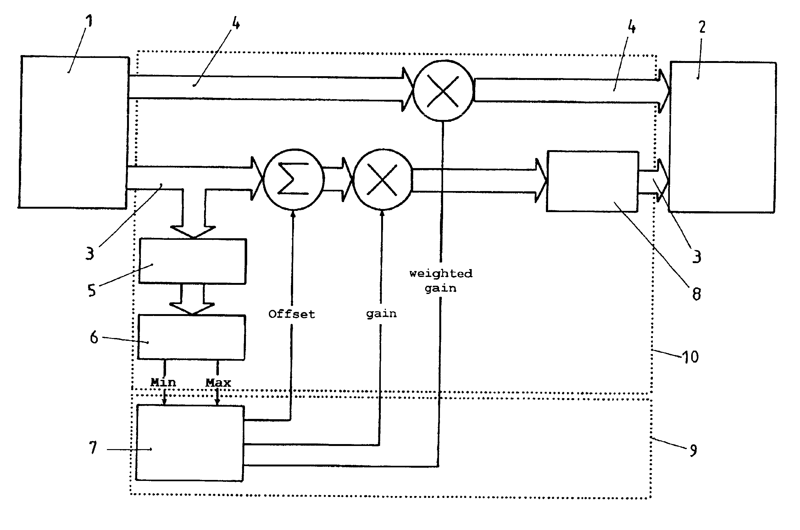
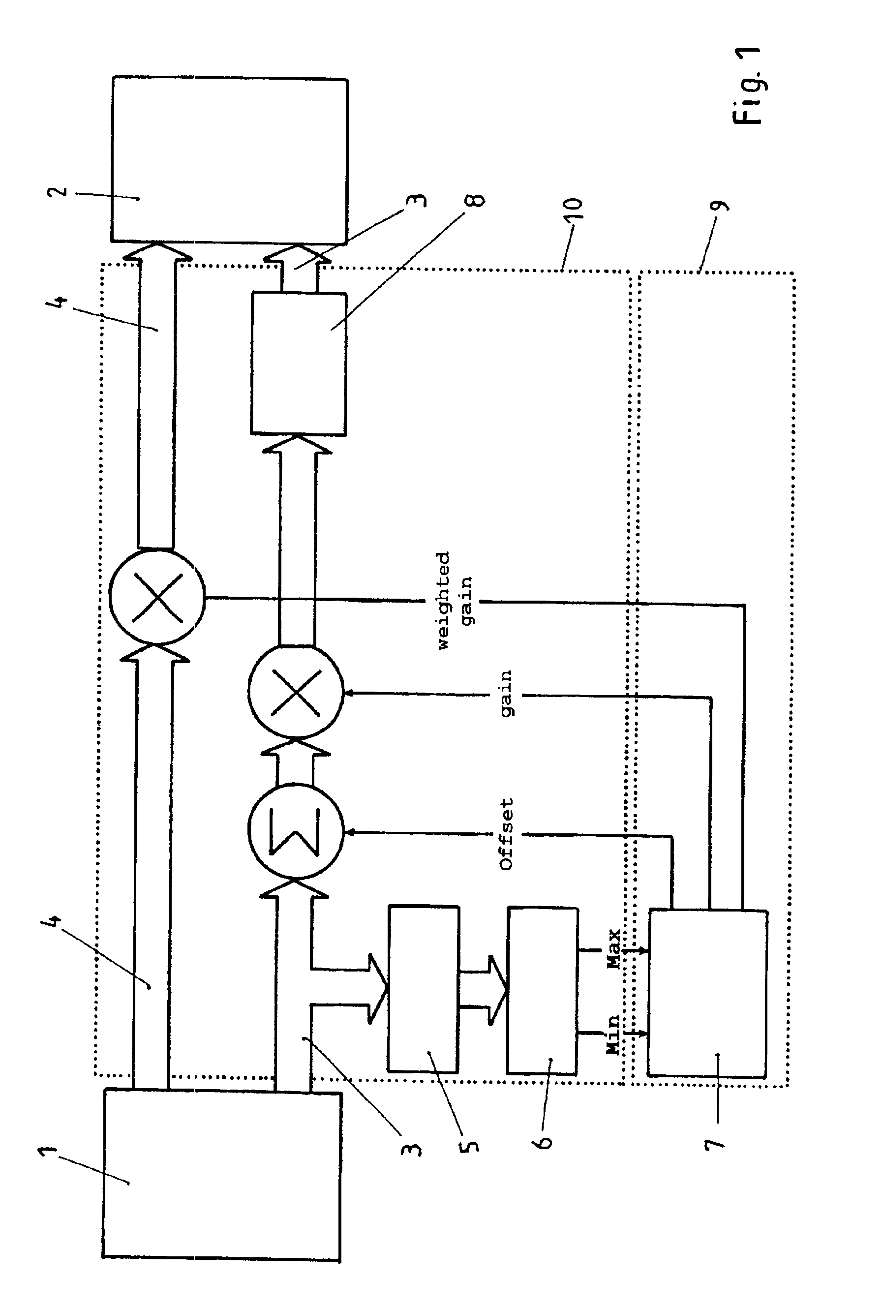
[0031]Referring now in greater detail to the drawings, FIG. 1 illustrates the principle of the novel method which starts from a digital video signal 1, and which outputs a modified video signal 2. In the illustrated exemplary embodiment, both video signals 1 and 2 are YUV signals of the type 4:2:2 according to video standard ITU-R BT.601 / 656. These digital video signals contain a brightness signal component 3 and a color signal component 4. The brightness signal component—which in this case is the Y component—according to ITU-R BT.601 / 656 has a value in the range of between 16 to 254, while the color signal—which in this case is the UV component and which is also called color difference signal—has values in a range of between 16 to 240. The latter value range (16-240) corresponds to 128±112, the value 128 representing a non-colored picture element.

[0032]The brightness signal component 3 is split to obtain a branch that can be evaluated. In this branch, step 5 levels or smoothens the...


PUM


Abstract

A method of improving a signal in an image sequence acquired with a digital color video camera creating a digital video signal (1) including a brightness signal component (3) and a color signal component (4) includes the steps (6, 7) of continuously evaluating the brightness signal component (3) to calculate maximum brightness values and minimum brightness values at least within a first predetermined image sector and at least for a partial sequence of images, continuously calculating offset values on the basis of at least two previously calculated minimum brightness values, continuously calculating gain values based on differences between at least to previously calculated maximum brightness values and the associated minimum brightness values, continuously modifying the brightness signal component (3) by subtracting the last calculated offset value therefrom and by then multiplying it with the last gain value, and continuously modifying the color signal component (4) by multiplying it with the last calculated gain value and a predetermined weighting factor at least for a second predetermined image sector.

Description

CROSS REFERENCE TO RELATED APPLICATIONS[0001]This application claims the benefit of co-pending German Patent Application No. 100 64 678.6-31 entitled “Verfahren zur Signalverbesserung in einer mit einer digitalen Farbvideokamera aufgenommenen Bilderfolge”, filed on Dec. 22, 2000.FIELD OF THE INVENTION[0002]The present invention generally relates to a method of improving a signal in an image sequence acquired with a digital color video camera. More particularly, the present invention relates to a method in which the color video camera creates a digital video signal consisting of a brightness signal component and a color signal component.BACKGROUND OF THE INVENTION[0003]Digital color video cameras which create a digital video signal consisting of a brightness signal component and a color signal component are known in the art. The two signal components are immediately transformed into an analog color video signal. The analog video signal is suitable for the conventional transmission of...

Claims


Application Information

Patent Timeline
IPC IPC(8): H04N9/68H04N5/20H04N5/202
CPCH04N5/20H04N9/68H04N5/202
Inventor HAESE, JUERGENWEYH, STEPHAN
Owner KAPPA OPTO ELECTRONICS
Why Eureka
Try Eureka