
Spatial separation and multi-polarization of antennae in a wireless network

Inactive Publication Date: 2005-11-08
INTEL CORP
View PDF15 Cites 46 Cited by
  • Summary
  • Abstract
  • Description
  • Claims
  • Application Information

AI Technical Summary

Benefits of technology

[0016]The invention includes an apparatus and a method for wirelessly transmitting data streams from multiple antennae. Spatial separation and polarization allows the transmitted data streams to be more effectively separated and de-correlated within a receiver, thereby improving spatial multiplexing and communication diversity. The apparatus and method allows for adaptive optimization of received signal separation and received signal de-correlation.
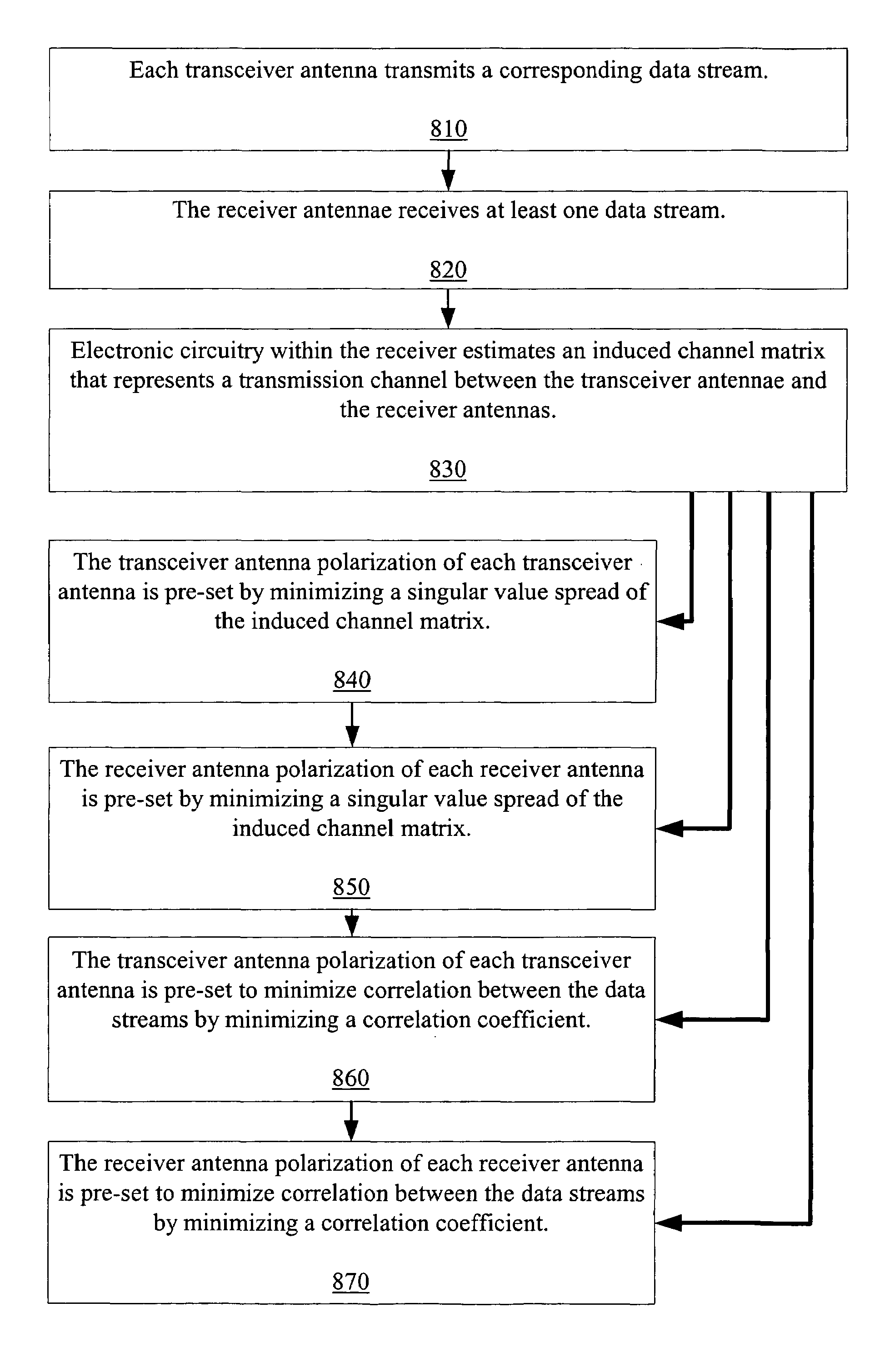
[0018]A second embodiment of the invention is similar to the first embodiment. The second embodiment further includes estimating a transmission channel between the transceiver antennae and the receiver antennae with a channel matrix. The pre-set transceiver antenna polarization of each transceiver antenna is determined by minimizing a singular value spread of the channel matrix.
[0019]A third embodiment is similar to the second embodiment. The third embodiment includes each receiver antenna being spatially separate from at least one other receiver antenna. Each receiver antenna further includes a receiver antenna polarization. At least one receiver antenna includes a polarization that is different than at least one other receiver antenna. The receiver includes electronic circuitry for estimating a transmission channel between the transceiver antennae and the receiver antennae with a channel matrix. The pre-set receiver antenna polarization of each receiver antenna is experimentally determined by minimizing a singular value spread of the channel matrix.
[0022]A sixth embodiment includes a method of wirelessly communicating between a transceiver and a receiver within a wireless communication system. The transceiver includes a plurality of transceiver antennae. Each transceiver antennae is spatially separate from at least one other transceiver antenna. Each transceiver antenna further includes a transceiver antenna polarization. At least one transceiver antenna has a polarization that is different than at least one other transceiver antenna. The receiver includes a plurality of receiver antennae. The method includes each transceiver antenna transmitting a corresponding data stream. The receiver antennae receive at least one data stream. Electronic circuitry within the receiver estimates a transmission channel between the transceiver antennae and the receiver antennae with a channel matrix. The transceiver antenna polarization of each transceiver antenna is pre-set by minimizing a singular value spread of the channel matrix.

Problems solved by technology

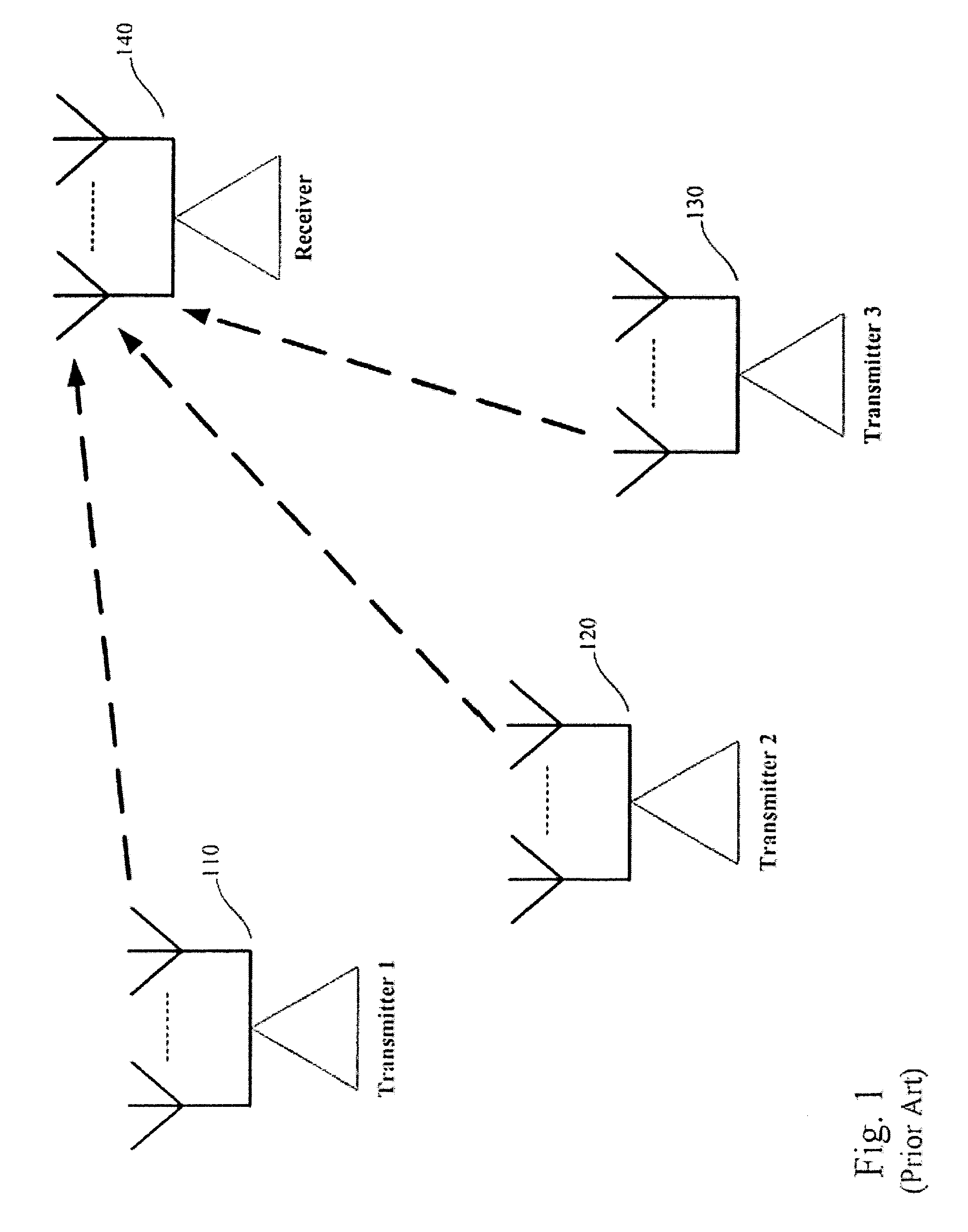
A limiting factor in the performance of spatial multiplexing systems is the ability of the receiver to separate the multiple transmitted signals.
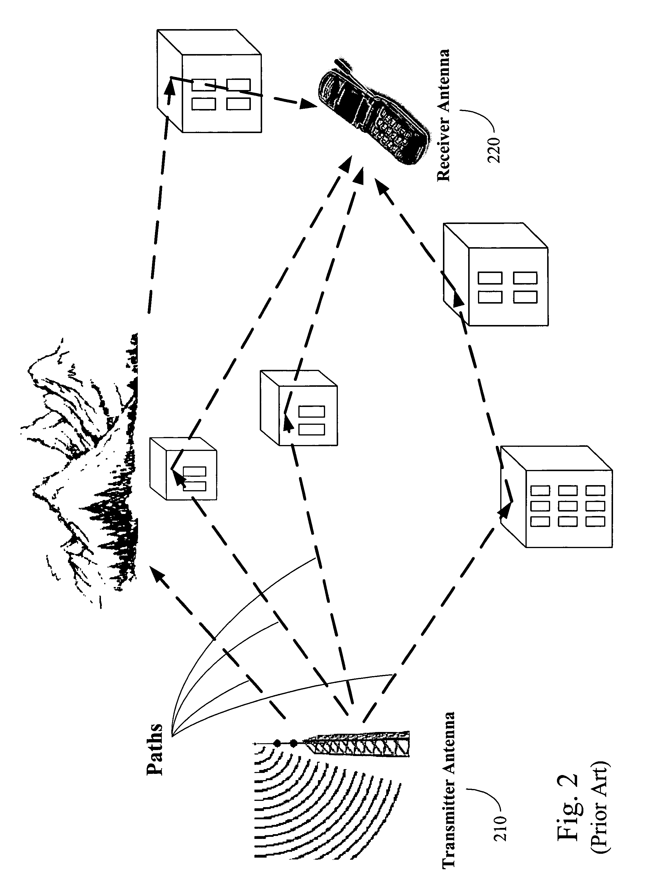
Due to this misalignment, the multipath signals can cause intersymbol interference or distortion of the received signal.
The multiple paths traveled by the modulated carrier signal typically results in fading of the modulated carrier signal.
Therefore, when one channel is fading due to the destructive effects of multi-path interference, another of the channels is unlikely to be suffering from fading simultaneously.
A limiting factor to the performance of communication diversity systems is the amount of correlation of the received signals with each other.

Method used


Image

  • Spatial separation and multi-polarization of antennae in a wireless network
  • Spatial separation and multi-polarization of antennae in a wireless network
  • Spatial separation and multi-polarization of antennae in a wireless network

Examples


Embodiment Construction

[0037]As shown in the drawings for purposes of illustration, the invention is embodied in an apparatus and a method for wirelessly transmitting data streams from multiple antennae. Spatial separation and polarization allows the transmitted data streams to be more effectively separated and de-correlated within a receiver, thereby improving spatial multiplexing and communication diversity. The apparatus and method allows for adaptive optimization of received signal separation and received signal de-correlation.

[0038]FIG. 3 shows an embodiment of the invention. This embodiment includes a wireless communication system. The wireless communication system includes a transmitter 300. The transmitter 300 includes several transmitter antennae 305, 310, 315. The transmitter antennae 305, 310, 315 are spatially separated from each other. Additionally, each transmitter antenna 305, 310, 315 includes a transceiver antenna polarization orientation. At least one of the transmitter antennae has a tr...


PUM


Abstract

The present invention includes a wireless communication system. The wireless communication system includes a plurality of transceiver antennae. Each transceiver is spatially separate from at least one other transceiver antenna. Each transceiver antenna includes a transceiver antenna polarization. At least one transceiver antenna has a polarization that is different than at least one other transceiver antenna. Each transceiver antenna transmits a corresponding data stream. The wireless communication system further includes a plurality of receiver antennae. The receiver antennae receive at least one data stream. The transceiver antenna polarization of each transceiver antenna is pre-set to optimize separability of the received data streams. A transmission channel between the transceiver antennae and the receiver antennae can be estimated with a channel matrix. The pre-set transceiver antenna polarization of each transceiver antenna can be determined by minimizing a singular value spread of the channel matrix. A pre-set receiver antenna polarization of each receiver antenna can also be determined by minimizing a singular value spread of the channel matrix.

Description

FIELD OF THE INVENTION[0001]The invention relates generally to wireless communications. More particularly, the invention relates to wireless communication through multiple antennae that are spatially separated and include multi-polarization for optimizing separation of transmitted and received data streams.BACKGROUND OF THE INVENTION[0002]Wireless communication systems commonly include information carrying modulated carrier signals that are wirelessly transmitted from a transmission source (for example, a base transceiver station) to one or more receivers (for example, subscriber units) within an area or region.[0003]Spatial Multiplexing[0004]Spatial multiplexing is a transmission technology that exploits multiple antennae at both the base transceiver station and at the subscriber units to increase the bit rate in a wireless radio link with no additional power or bandwidth consumption. Under certain conditions, spatial multiplexing offers a linear increase in spectrum efficiency wit...

Claims


Application Information

Patent Timeline
IPC IPC(8): H04B7/02H04L1/02H04B7/10
CPCH04B7/10
Inventor GESBERT, DAVID J.SEBASTIAN, PEROOR K.ERCEG, VINKOSHTROM, VICTORKASTURIA, SANJAYPAULRAJ, AROGYASWAMI J.
Owner INTEL CORP
Learn More