Power source for a dispersion compensation fiber optic system

a fiber optic system and power source technology, applied in the field of fiber optic system power source, can solve the problems of high chirping output, increased system power penalties to unacceptable levels, limited use of direct modulated lasers, etc., and achieve the effect of minimizing the degradation of signal caused by fiber dispersion

Inactive Publication Date: 2005-11-08
OPTICAL HORIZONS CORP +1
View PDF9 Cites 121 Cited by
  • Summary
  • Abstract
  • Description
  • Claims
  • Application Information

AI Technical Summary

Benefits of technology

[0011]This invention provides an optical discriminator capable of operating with a frequency modulated (FM) source at high bit rates and having dispersion that is opposite sign of the dispersion in the transmission fiber to neutralize at least some portion of the dispersion in the fiber. With the discriminator providing dispersion that is opposite sign of the dispersion in the fiber, signal degradation due to dispersion in the fiber is minimized. This invention also provides a modulated laser source and a discriminator system that compensates for the fiber dispersion as well as converting a partially frequency modulated signal into a substantially amplitude modulated signal. With the discriminator that counters the dispersion in the fiber, the laser source may be directly modulated for longer reach applications.
[0012]The discriminator may be a variety of filters such as a coupled multi cavity (CMC) filter to enhance the fidelity of converting a partially frequency modulated signal into a substantially amplitude modulated signal as well as introducing enhanced dispersion that is opposite sign of the dispersion in the fiber so that the optical signal may propagate further distances without being distorted. This invention may also provide a modulated laser source that is communicatably coupled to an optical filter where the filter is adapted to lock the wavelength of a laser source as well as converting the partially frequency modulated laser signal into a substantially amplitude modulated signal.

Problems solved by technology

One of the drawbacks of a directly modulated transmitter, however, is that its output is highly chirped.
Chirped pulses become distorted after propagation through tens of km of dispersive optical fiber, increasing system power penalties to unacceptable levels.
This has limited the use of directly modulated laser, transmitters to applications with limited distances of tens of km at 2.5 Gb / s as described by P. J. Corvini and T. L. Koch, Journal of Lightwave Technology vol.
For higher bit rate applications, the use of directly modulated transmitters may be limited to even shorter distances.
In the conventional directly modulated laser transmitter, chirp causes severe pulse distortion upon propagation through the optical fiber.
This is because the speed of light in the dispersive medium is frequency dependent, frequency variations of pulses may undergo different time delays, and thus the pulse may be distorted.
If the propagation distance through the medium is long as in the case of optical fibers, the pulse may be dispersed in time and its width broadened, which has an undesirable effect.
However, the steeper the transmission edges, the narrower the pass-band of the filter.
As such, Fabry-Perot filter may provide the steeper transmission edges or slope, but it does not provide the broad enough bandwidth for high bit rate applications such as 10 Gb / s.
At higher bit rates, the spectrum of the frequency modulated signal becomes more complicated and the choice of discriminators that may be used is limited.
In addition, the transient chirp that arises at the transitions between 1s and 0s broadens to complicate the spectrum further.
Under these performance criteria, a Fabry-Perot filter may not work because the bandwidth and slope characteristics of Fabry-Perot filters are such that the steeper the transmission edges, the narrower the pass-bandwidth of the filter.
Such limited bandwidth can severely distort a 10 Gb / s signal such that the FM modulated transmitter with a Fabry-Perot filter may not work at this bit rate.
Others have tried fiber Bragg gratings for high bit rate applications, but these are sensitive to temperature and require separate package with temperature stabilization.

Method used


Image

  • Power source for a dispersion compensation fiber optic system
  • Power source for a dispersion compensation fiber optic system
  • Power source for a dispersion compensation fiber optic system

Examples


Embodiment Construction

[0045]This invention provides a laser transmitter system capable of directly modulating a laser source and partially compensating for the dispersion in the fiber so that the system may be applied to faster bit rate and longer reach applications. This may be accomplished by providing a discriminator that converts frequency modulation (FM) to amplitude modulation (AM) and compensate for the dispersion in the optical fiber so that the laser source may be directly modulated. A variety of discriminators may be used such as a coupled multi-cavity (CMC) filter to enhance the fidelity of FM / AM action as well as introducing enhanced dispersion compensation. By simultaneously optimizing the FM to AM conversion as well as the dispersion compensation properties, the performance of directly modulating the laser source may be optimized.

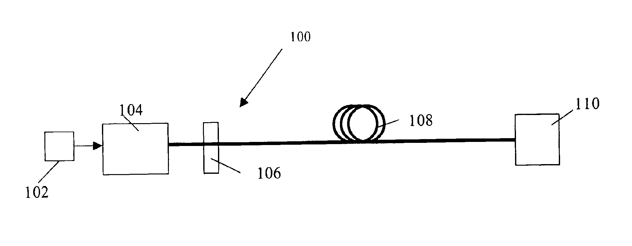
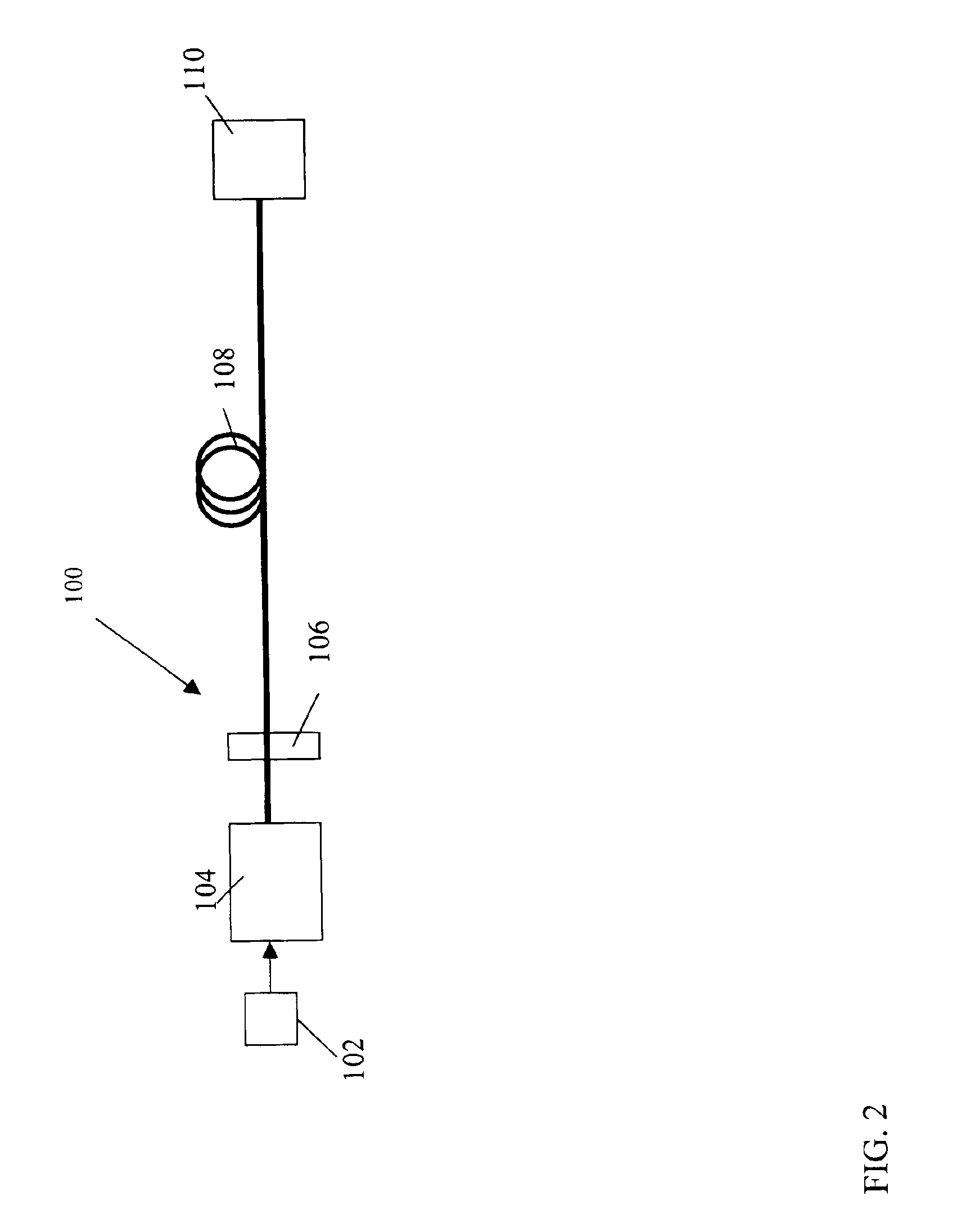
[0046]FIG. 2 illustrates a fiber optic system 100 that includes a current modulator 102 that modulates a laser source 104. The current modulator 102 may directly m...


PUM


Abstract

This invention generally relates to an optical filter for a fiber optic communication system. An optical filter may be used, following a directly modulated laser source, and converts a partially frequency modulated signal into a substantially amplitude modulated signal. The optical filter may compensate for the dispersion in the fiber optic transmission medium and may also lock the wavelength of the laser source.

Description

[0001]This application claims priority to two U.S. provisional applications: (1) U.S. Application No. 60 / 395,161, filed Jul. 9, 2002; and (2) U.S. Application No. 60 / 401,419, filed Aug. 6, 2002, which are both hereby incorporated by reference.BACKGROUND OF THE INVENTION[0002]1. Field of the Invention[0003]This invention generally relates to a power source for a fiber optic system that converts a partially frequency modulated signal into a substantially modulated signal and compensates for dispersion in a transmission fiber.[0004]2. General Background and State of the Art[0005]Fiber optic communication systems use a variety of transmitters to convert electrical digital bits of information into optical signals that are sent through optical fibers. On the other end of the optical fiber is a receiver that converts the optical signal to an electrical signal. The transmitters modulate the signals to form bits of 1s and 0s so that information or data may be carried through the optical fibe...

Claims


Application Information

Patent Timeline
Patent Type & Authority Patents(United States)
IPC IPC(8): G02B5/28G02B6/34H04B10/155H04B10/152H04B10/18
CPCG02B5/281G02B6/29358G02B6/29362G02B6/29394H04B10/25133H04B10/504H04B10/58G02B6/29398
Inventor MAHGEREFTEH, DANIELTAYEBATI, PARVIZ
Owner OPTICAL HORIZONS CORP
Why Eureka
Try Eureka