Combined transmitter

a transmitter and receiver technology, applied in the field of transmitters, can solve problems such as failure of the transfer lvds technology to external desktop monitors

Active Publication Date: 2005-04-28
VIA TECH INC
View PDF4 Cites 21 Cited by
  • Summary
  • Abstract
  • Description
  • Claims
  • Application Information

AI Technical Summary

Benefits of technology

[0002] The invention relates to a transmitter, and more particularly, to a combined transmitter capable of transmitting low voltage differential signaling (LVDS) and transition minimized differential signaling (TMDS).

Problems solved by technology

LVDS technology, optimized for short cable runs in an effort to transition LVDS technology to external desktop monitors failed.

Method used


Image

  • Combined transmitter
  • Combined transmitter
  • Combined transmitter

Examples


first embodiment

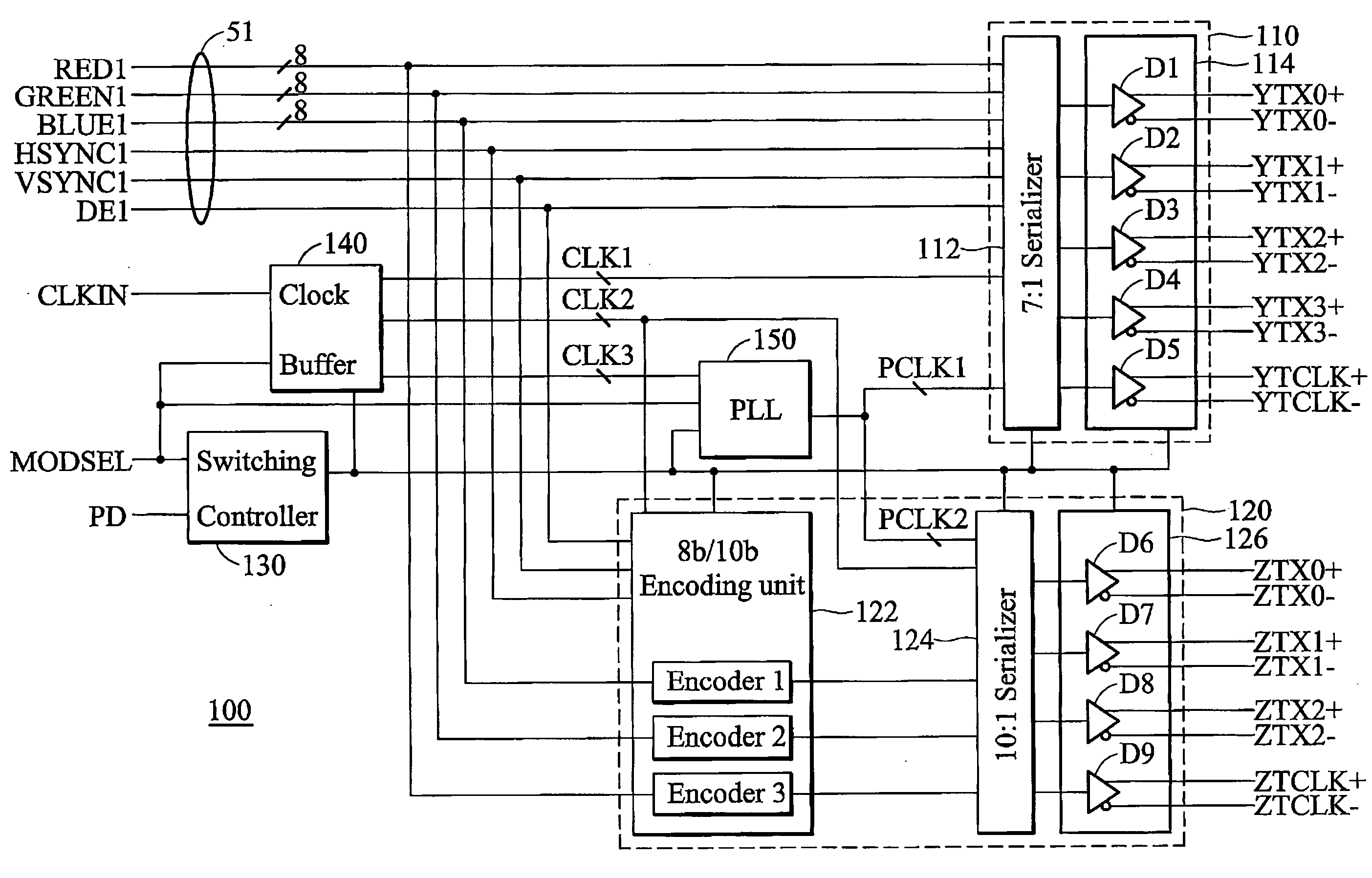
[0029]FIG. 3A is a schematic diagram of a combined transmitter capable of transmitting LVDS signals and TMDS signals according to a first embodiment of the invention. As shown in FIG. 3A, the combined transmitter 100 comprises a first set of input terminals 51, a first transmission unit 110, a second transmission unit 120, a switching controller 130, a clock buffer 140 and a phase locked loop (PLL) 150. The set of input terminal 51 receives first data comprising video and sync information (RED1, GREEN1, BULE1, HSYNC1, VSYNC1 and DE1).

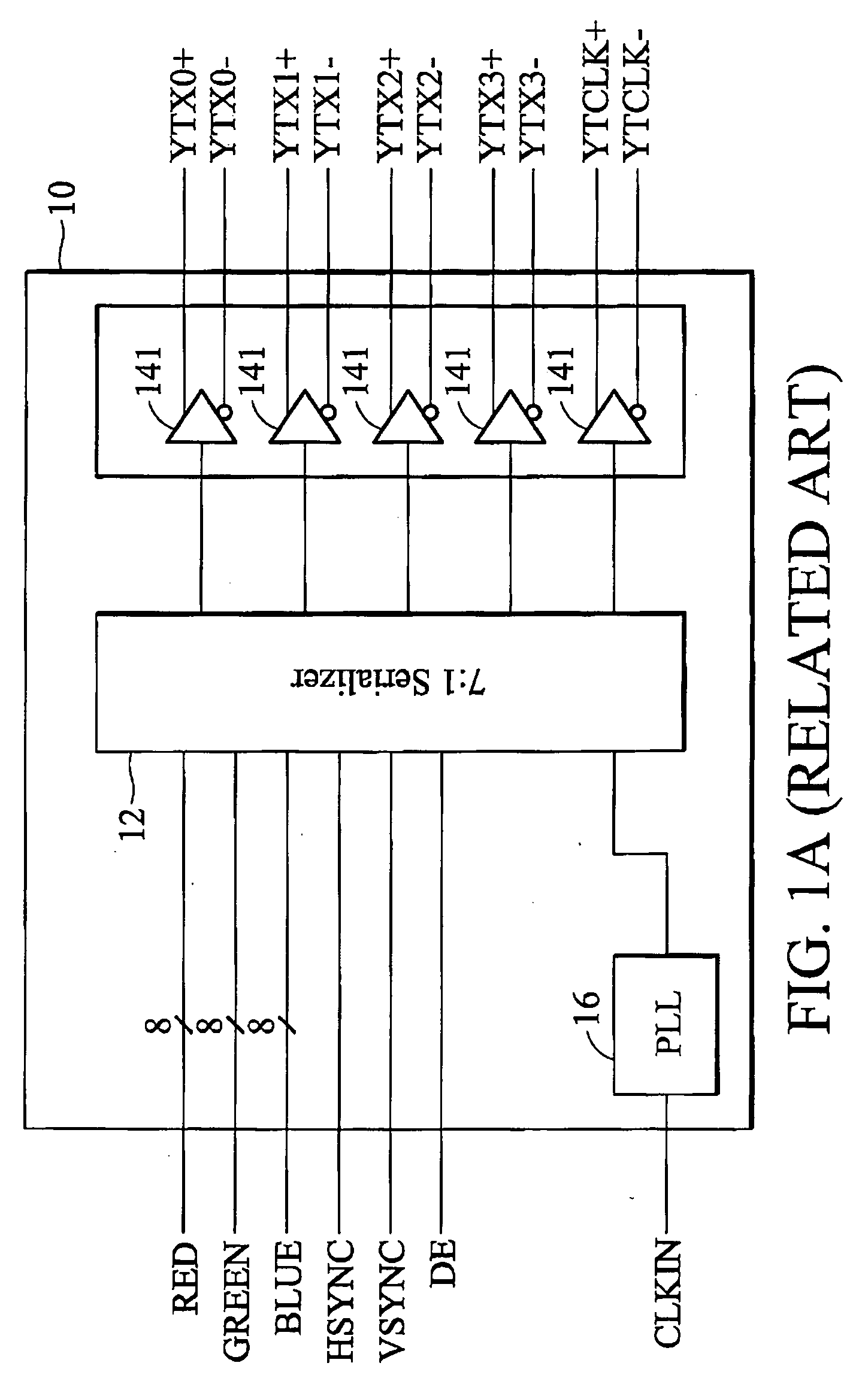
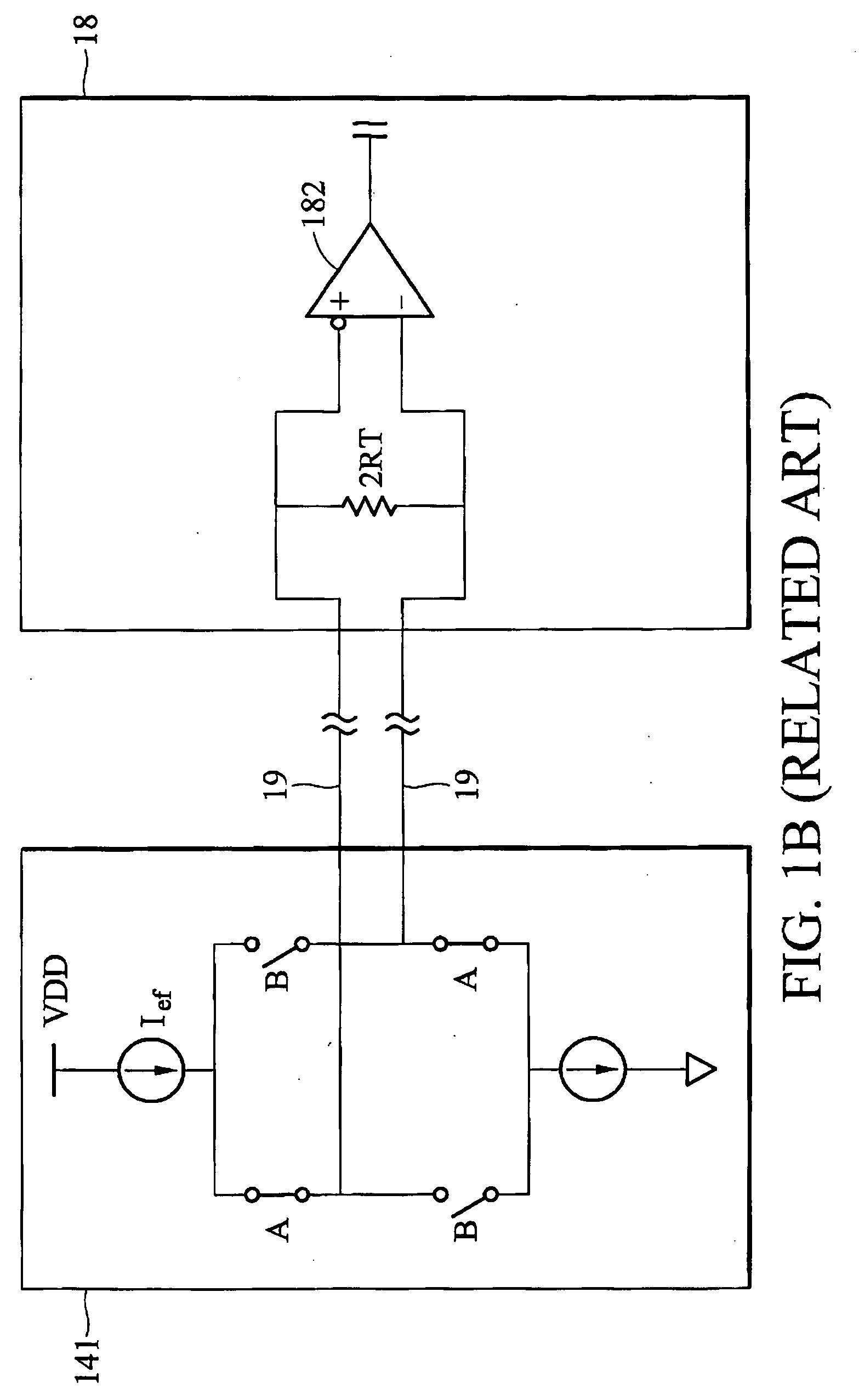
[0030] The first transmission unit 110 can be a LVDS transmitter as shown in FIGS. 1A and 1B. The first transmission unit 110 is coupled to the input terminals 51 to transmit first data, through the first signal lines YTX0+˜YTX3+, YTX0−˜YTX3−, YTCLK+ and YTCLK−, to a corresponding receiver (not shown). The first transmission unit 110 comprises a first serializer 112 coupled to the input terminals. 51 to convert parallel data to serial data streams and ...

second embodiment

[0046]FIG. 3B is a schematic diagram of a combined transmitter capable of transmitting LVDS signals and TMDS signals according to a second embodiment of the invention. As shown in FIG. 3B, the combined transmitter 100′ comprises a first set of input terminals 51, a first transmitter 110, a second transmitter 120, a switching controller 130, a clock buffer 140 and a phase locked loop (PLL) 150.

[0047] The combined transmitter 100′ is similar to that shown in FIG. 3A except for the driving unit 126. For brevity, description of like structures is omitted. The drivers D6˜D9 are coupled to the signal lines YTX1+˜YTX3+, YTX1−˜YTX3−, YTCLK+ and YTCLK− coupled to the driving unit 114 in the first transmission unit 110, rather than the signal lines ZTX0+˜ZTX2+, ZTX0−˜ZTX2−, ZTCLK+˜ZTCLK− as shown in FIG. 3A. The first and second transmission units 110 and 120 share the input terminals 51 and the output terminals, such as the signal lines YTX1+˜YTX3+, YTX1−˜YTX3−, YTCLK+˜YTCLK−.

[0048] In LVD...

third embodiment

[0052]FIG. 3C is a schematic diagram of a combined transmitter capable of transmitting LVDS signals and TMDS signals according to a third embodiment of the invention. As shown in FIG. 3C, the combined transmitter 100″ comprises a first set of input terminals 51, a second set of input terminals 52, a first transmitter 110, a second transmitter 120, a switching controller 130, a clock buffer 140 and a phase locked loop (PLL) 150.

[0053] The combined transmitter 100″ is similar to that in FIG. 3A except for the encoding unit 122 and the driving unit 126. For brevity, description of like structures is omitted. The second set of input terminals 52 receives second data comprising video and sync information RED2, GREEN2, BULE2, HSYNC2, VSYNC2 and DE2. The encoding unit 122 in second transmission unit 120 is coupled to the second set input terminals 52, rather than the first set of input terminals 51 as shown in FIG. 3A. Further, the drivers D6˜D9 in the second driving unit 126 are coupled ...


PUM


Abstract

A combined transmission unit for TMDS signals and LVDS signals. A first (LVDS) transmission unit includes a set of first input terminals to receive first data, and a second (TMDS) transmission unit includes a set of second input terminals to receive second data. A phase locked loop (PLL) generates a first set of output clock signals to the first transmission unit in a first mode and a second set of output clock signals to the second transmission unit in a second mode according to a mode selection signal. The first and second transmission units are able to transmit the first data to the first and second external input units in the first and second modes respectively, according to the mode selection signal and the first and second sets of output clock signals.

Description

[0001] This application claims the benefit of U.S. Provisional application No. 60 / 514,606, filed on Oct. 28, 2003.BACKGROUND [0002] The invention relates to a transmitter, and more particularly, to a combined transmitter capable of transmitting low voltage differential signaling (LVDS) and transition minimized differential signaling (TMDS). [0003] Low Voltage Differential Signaling (LVDS) is a high-speed, low power interface used by most notebook computer manufactures to create a direct digital connection between the central processing unit (CPU) and LCD display. It provides very high line transmission rate, requires little power and generates low noise levels. LVDS technology, optimized for short cable runs in an effort to transition LVDS technology to external desktop monitors failed. [0004]FIG. 1A shows a conventional LVDS transmitter 10. The LVDS transmitter 10 converts data (RED, GREEN, BLUE, HSYNC, VSYNC and DE) to data streams for output to a corresponding receiver through si...

Claims


Application Information

Patent Timeline
Patent Type & Authority Applications(United States)
IPC IPC(8): G09G5/00H04B1/04H04B1/18
CPCH04L25/0272G09G3/20H04B1/18G09G3/36H04B1/04
Inventor CHENG, YU-FENGLIU, WEN-BOLI, KEN-MINGAU, VAI-HANGSONG, ZHEN-YU
Owner VIA TECH INC
Why Eureka
Try Eureka