
Localized application of high impedance fault isolation in multi-tap electrical power distribution system

a multi-tap electrical power distribution system and high impedance fault technology, applied in the direction of fault location by conductor type, short-circuit testing, instruments, etc., can solve the problem of inability to distinguish low fault current (high impedance fault) from normal load current, and the application of overcurrent protection devices

Inactive Publication Date: 2018-08-16
ELECTRICAL MATERIALS
View PDF2 Cites 20 Cited by
  • Summary
  • Abstract
  • Description
  • Claims
  • Application Information

AI Technical Summary

Benefits of technology

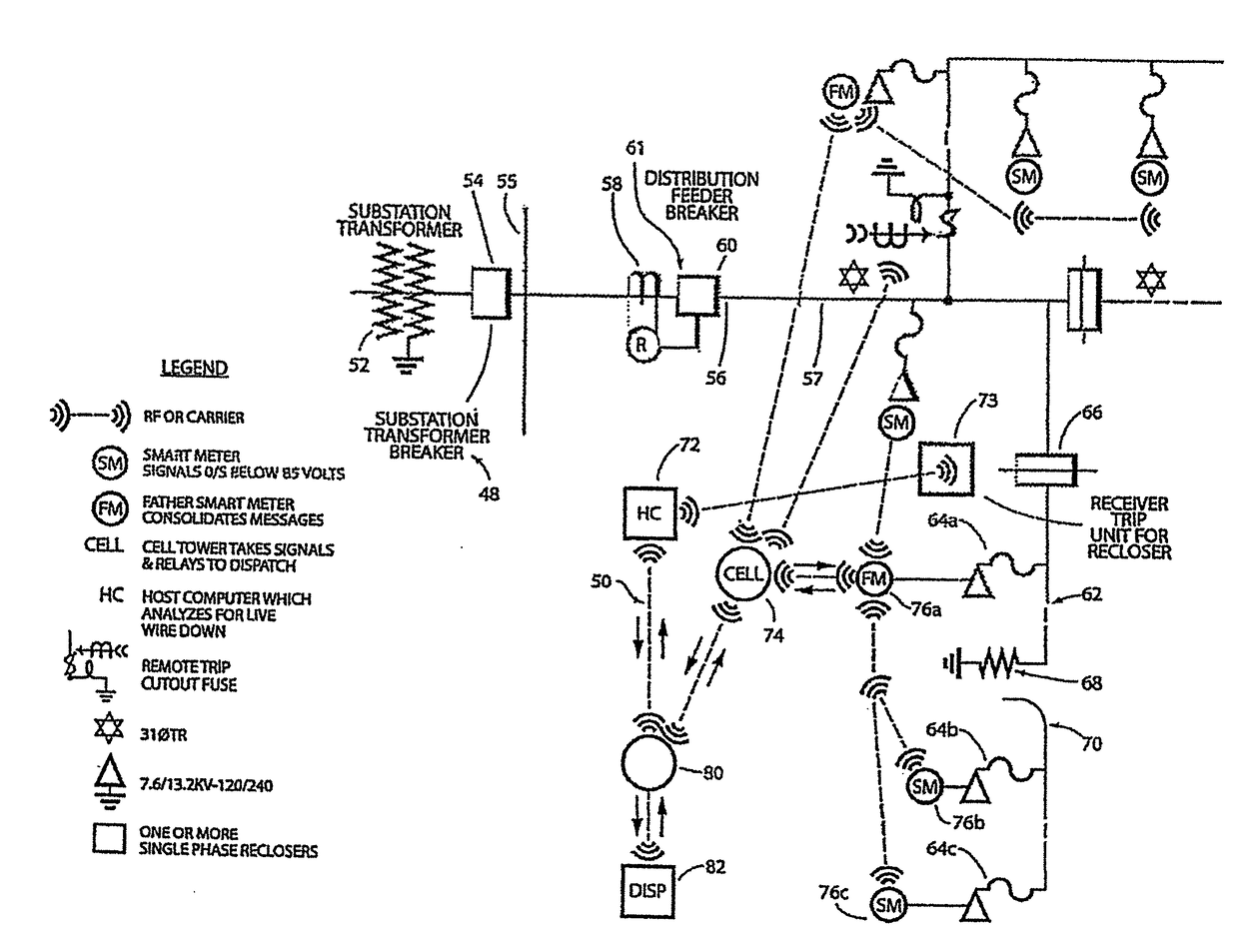
The present invention aims to quickly detect, isolate, and de-energize a faulted electric utility conductor in a multi-tap, or multi-branch, network without involving other standard portions of the network's fault analysis and isolation package. The invention provides a fast and efficient way to isolate and shut down high impedance, low fault current in an high voltage electrical power distribution network. This minimizes the time it takes to process signals and ensures safer and reliable protection of the power distribution network.

Problems solved by technology

High impedance, low current faults, such as a downed distribution line conductor in an electric utility distribution network which is contacting a poor conductive earth composite, have proven to be difficult to isolate with present technology.
A particularly difficult situation for detecting a high impedance fault in an electrical distribution system incorporating a live conductor downed, but intact, where the conductor is grounded through a poor conducting medium such as sand, rock, concrete, snow, blacktop or a dead tree.
Present applied overcurrent protection devices are, however, unable to distinguish low fault currents (high impedance faults) from normal load currents because trip settings for these devices are typically set at 125 to 250 percent of maximum estimated peak load current.
Isolating devices with more sensitive protection have recently been introduced, but still require a certain minimum value of fault current and have no automated means of clearing for a zero current flow.
A hazardous condition for the public is created when energized high voltage conductors fall to the ground or come in contact with a high impedance fault current return path, and the overcurrent protection system fails to de-energize the conductor.
Physical contact with an energized distribution primary conductor by any conducting body may cause serious injury or death due to electric shock.
Numerous fatalities and serious injuries occur annually in the United States due to inadvertent contact with live down power distribution conductors.
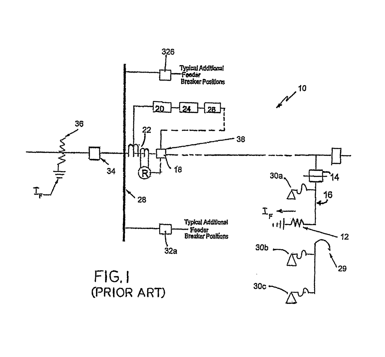
While the arrangement shown in FIG. 1 is designed for detection and shutdown of high voltage (low impedance) faults involving large currents, it is incapable of detecting and isolating high voltage ground faults accompanied by minimal ground fault currents due to variable high impedance faults.
This downed wire constitutes a very high impedance fault characterized by a limited fault current typically below the tripping value of the associated fault isolating device.
The electrical equivalent circuit of this operation is paralleling a bolted phase to ground minimal impedance with the high impedance downed wire conductor, resulting in increased fault current to trip the isolating device.

Method used


Image

  • Localized application of high impedance fault isolation in multi-tap electrical power distribution system
  • Localized application of high impedance fault isolation in multi-tap electrical power distribution system
  • Localized application of high impedance fault isolation in multi-tap electrical power distribution system

Examples


Embodiment Construction

[0024]Referring to FIG. 3, there is shown in simplified schematic diagram form the involved components on a single phase utility overhead distribution circuit tap 200 which is adapted to clear a live wire down fault in accordance with one embodiment of the present invention. Single phase tap 200 includes a mainline feeder 122 carrying electrical energy from a power source (not shown in the figure). Mainline feeder 122 is coupled to and supported by an electric pole 124 having an attached first cross member 121.

[0025]Attached to a second cross member 123 on the electric pole 124 is a primary tap fuse isolator 201 and a trouble primary tap 202 which was previously formed with and attached to a now broken primary wire 203 which includes a high impedance fault 126. Trouble primary tap 202 represents a portion of the primary tap which is still electrically alive. Attached to the trouble portion of the primary tap 202 is a serially coupled combination of a first transformer 204 and a firs...


PUM


Abstract

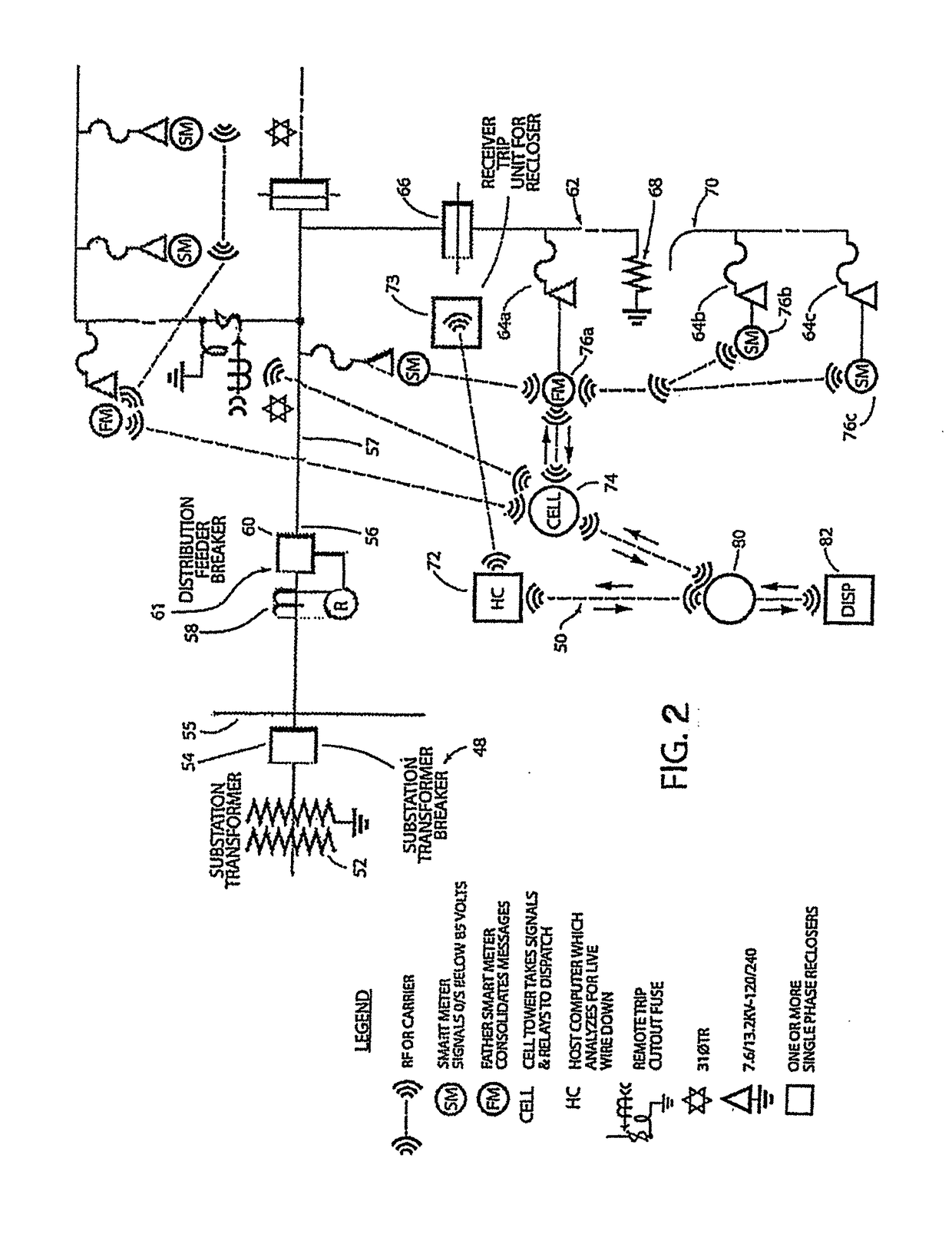
A high impedance fault isolation system (HIFIS) identifies, isolates and dissipates high impedance, low current faults which occur within an individual tap, or branch, of an electric power distribution system using only portions of the tap affected. A master meter, or father smart meter (FSM), on the affected tap sends a coded signal to an antenna receiver combined with a microprocessor and chip which operates an electromagnetic control (EMC) grounding spring switch which isolates the downed primary conductor by causing the distribution system protecting device, i.e., a high voltage fuse or recloser, to de-energize the downed primary wire. This localized application of the HIFIS at the individual tap level allows the FSM to analyze and determine, for example, that the specific field condition is a “downstream wire down”, and that the installed isolating device has failed to operate because of insufficient fault current, allowing the localized intervention of the HIFIS to achieve the de-energization more efficiently and safely, and within a much shorter time period. A fire door sensor circuit then receives the trip signal from the microprocessor, causing the fire door sensor to melt open and release a shorting spring, in initiating operation of an expulsion fuse or recloser, which kills the downed live wire.

Description

FIELD OF THE INVENTION[0001]This invention relates generally to apparatus for sensing, isolating and de-energizing a downed alternating current electric utility primary distribution circuit conductor which has developed into a high impedance fault which overcurrent protection devices or high impedance detection systems have been unable to clear. This dangerous condition may occur at any location on an electrical utility distribution circuit due to lack of conductivity of the earth in the fault current return path. In some instances, the line impedance due to the distance of the ground fault from the substation source combined with high fault impedance at the wire down location may limit the ground fault current to a value less than the normal actual load current at this location. There is a need for a fault isolating package that has no limitation on distance limits or fault current value.[0002]A type of high impedance fault condition may also occur when a high voltage primary condu...

Claims


Application Information

Patent Timeline
Patent Type & Authority Applications(United States)
IPC IPC(8): H02H3/08G01R31/02
CPCG01R31/025H02H3/083H02H3/042H02H7/261G01R31/086G01R31/52H02J13/00026H02J13/00034H02J13/0004Y04S10/52
Inventor O'REGAN, TIMOTHY M.O'REGAN, TIMOTHY J.HAYES, THOMAS M.
Owner ELECTRICAL MATERIALS
Learn More