[0011]A fiber management frame and an interconnection closure including the fiber management frame are provided for securely retaining
optical fiber connection trays once the splice closure has been placed in service, while also permitting ready access to any one of the trays to reconfigure the connections housed by the respective tray without moving or otherwise repositioning the remaining trays. Accordingly, the fiber management frame and the associated interconnection closure of the present invention protect the connections housed by the trays from inadvertent damage otherwise possibly occasioned by
unintended movement of the trays.
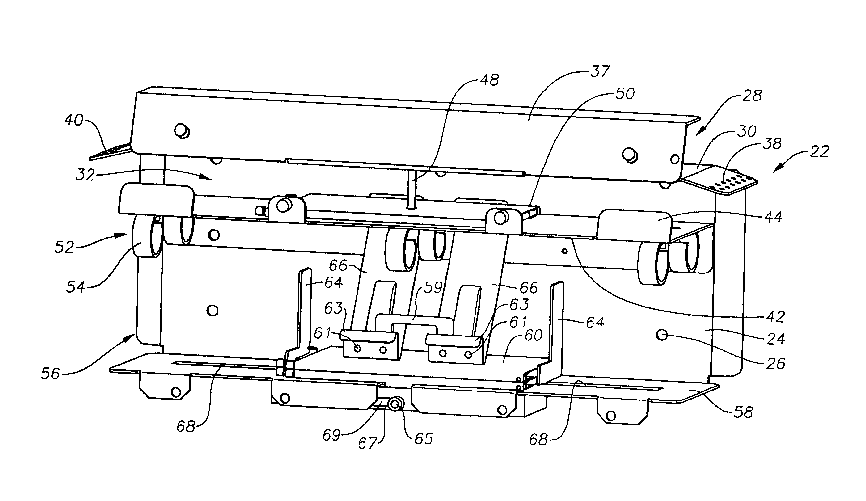
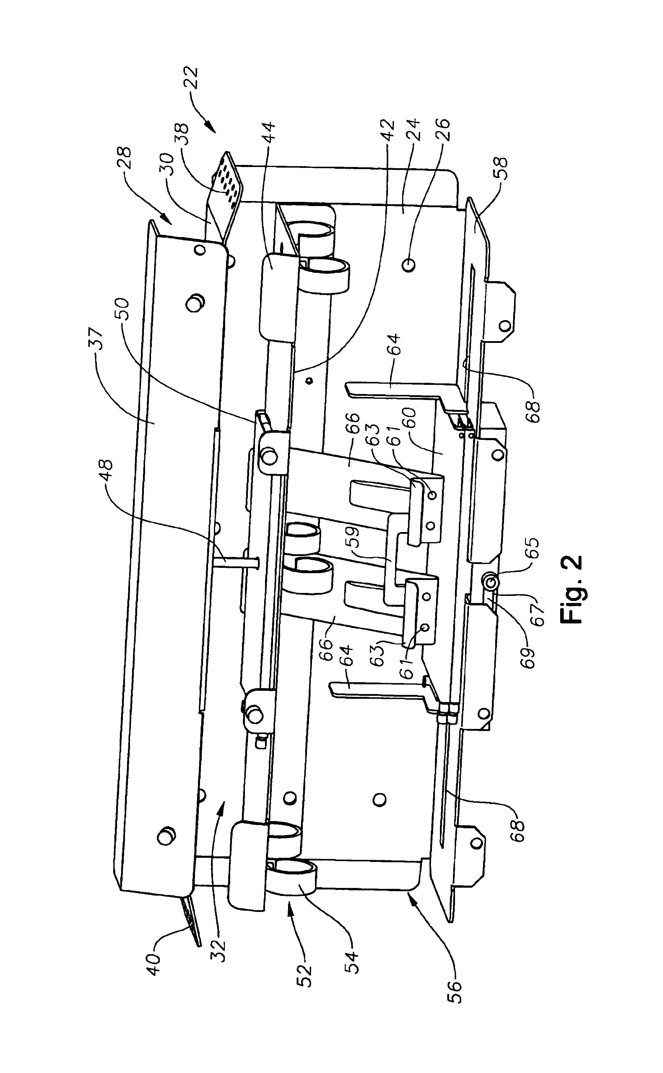
[0012]According to one aspect of the present invention, a fiber management frame is provided that includes a support for holding at least one optical fiber connection tray selected from the group consisting of a splice tray, a coupler tray, and a connector panel, and a bias member for urging each such tray toward the support. As such, the bias member releasably secures each tray within the fiber management frame. The bias member preferably includes at least one
tension member extending toward the support, thereby typically defining an
acute angle with respect to the support. The
tension member is capable of exerting a force having a component directed toward the support to secure each tray within the fiber management frame. Typically, each
tension member extends from a first end that is remote from the support to a second end that is
proximate the support. In order to facilitate lifting of a tension member in order to insert a tray, the second end of the tension member preferably includes an upturned lip that can be readily engaged by a
technician. In a further embodiment, the bias member is formed by a pair of tension members that are spaced apart from one another. To facilitate movement of the pair of tension members in tandem, the tension members may be interconnected by a
handle.
[0014]Regardless of the number of trays stacked upon the support, the bias member imparts a force upon each of the trays that urges the trays toward the support, thereby securing the trays in position between the bias member and the support. Since the bias member generally contacts the tray that is furthest removed from the support and does not otherwise extend about the trays, any tray, including a tray in the middle of the stack or a tray on the bottom of the stack, can be removed without having to move or otherwise reposition the upper trays. Thus, the connections housed by any of the trays can be reconfigured without having to remove the overlying trays. Moreover, the bias member can continue to impart a force to the trays that urges the trays toward the support even as one or more trays are being removed, thereby effectively preventing the type of undesirable movement of the trays relative to the fiber management frame or relative to one another that typically results upon the release of a strap of a conventional closure. Thus, the fiber management frame of this aspect of the present invention further protects the connections between respective pairs of the optical fibers by limiting undesired movement of the trays while facilitating reconfiguration of the connections housed by any one of the trays.
[0015]According to another aspect of the present invention, a fiber management frame is provided that includes a support and at least one adjustable member cooperating with the support to define a space for housing at least one tray selected from a group consisting of a splice tray, a coupler tray, and a connector panel. According to this aspect of the present invention, the at least one adjustable member is capable of being repositioned relative to the support so as to correspondingly resize the space. The space can therefore be resized to snugly receive trays having various sizes, thereby further preventing undesirable movement of the trays.
[0018]By including at least one and, more typically, a pair of adjustable members, such as a pair of upstanding brackets, the fiber management frame may be configured to snugly receive various sizes of trays. Thus, the fiber management frame of this aspect of the present invention can further reduce the movement of the trays once the splice closure has been configured and placed into service. The fiber management frame of this aspect of the present invention can therefore further protect the connections housed by the tray from inadvertent damage attributable to
unintended movement of the trays relative to one another and relative to other portions of the fiber management frame.
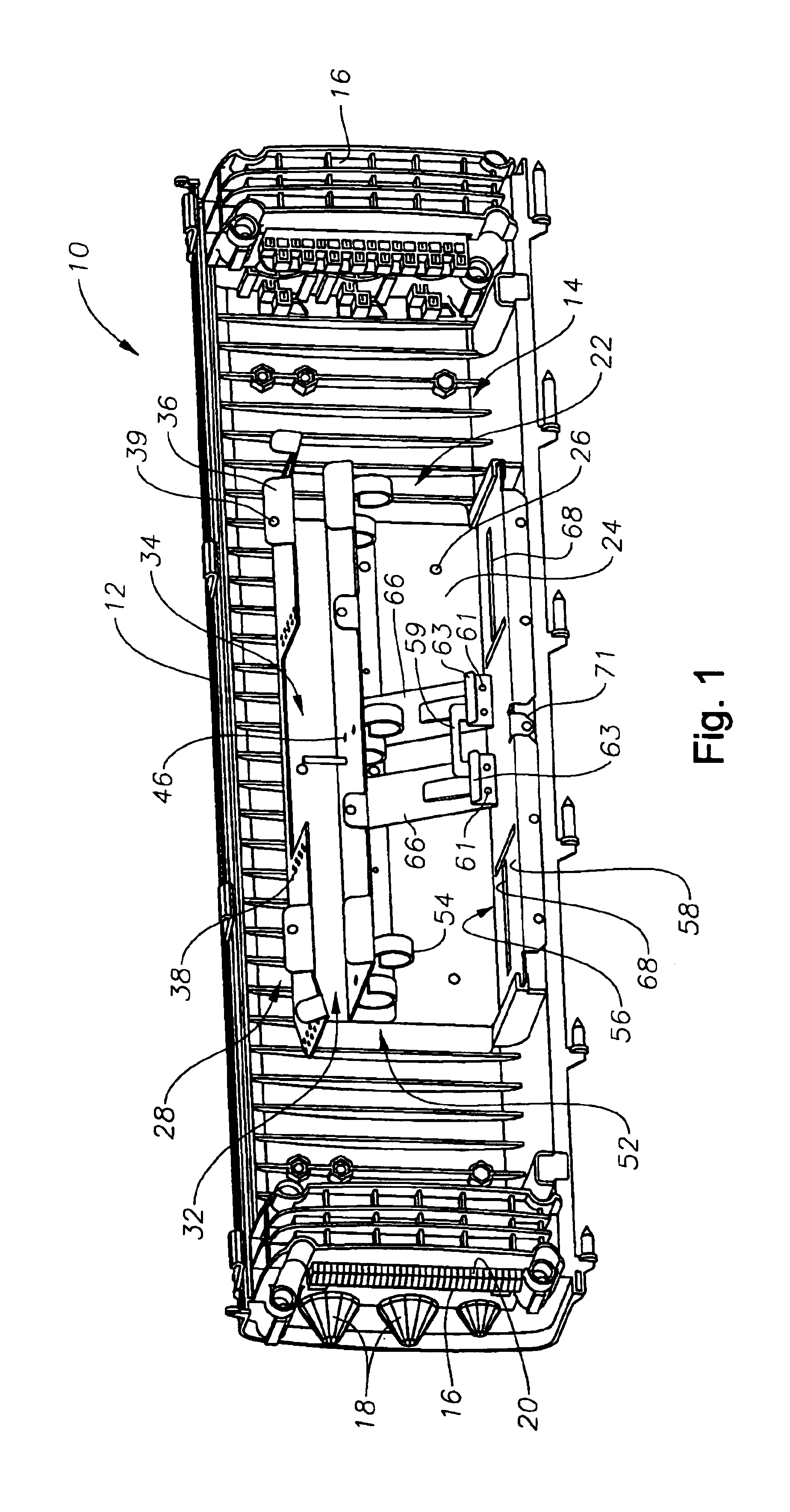
[0019]In addition to the various aspects of the fiber management frame described above, interconnection closures are also provided including respective fiber management frames. For example, an interconnection closure may include a fiber management frame having a bias member for releasably securing at least one tray in position and / or at least one adjustable member for defining the space in which trays will be housed. In addition to the fiber management frame, the interconnection closure includes a housing defining an
internal cavity in which the fiber management frame is disposed. The housing of the interconnection closure also defines a plurality of ports opening into the
internal cavity for receiving a plurality of cables. As described above in conjunction with the fiber management frame, the interconnection closure protects the connections housed by the trays from inadvertent damage while facilitating access by a
technician, such as during reconfiguration of the closure, by preventing the undesirable movement of the trays once the closure has been appropriately configured and placed into service.

