
Fluid flow measurement device

a flow measurement and sensor technology, applied in liquid/fluent solid measurement, process and machine control, instruments, etc., can solve the problems of low cost electronic, low cost, and generally unfavorable disposable use of fluid flow measurement systems, and achieve convenient compression of the second fluid flow passage, the effect of convenient compression

Inactive Publication Date: 2005-11-15
ICU MEDICAL INC
View PDF13 Cites 80 Cited by
  • Summary
  • Abstract
  • Description
  • Claims
  • Application Information

AI Technical Summary

Benefits of technology

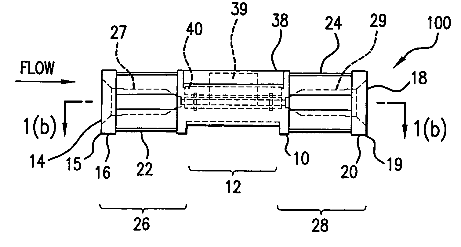
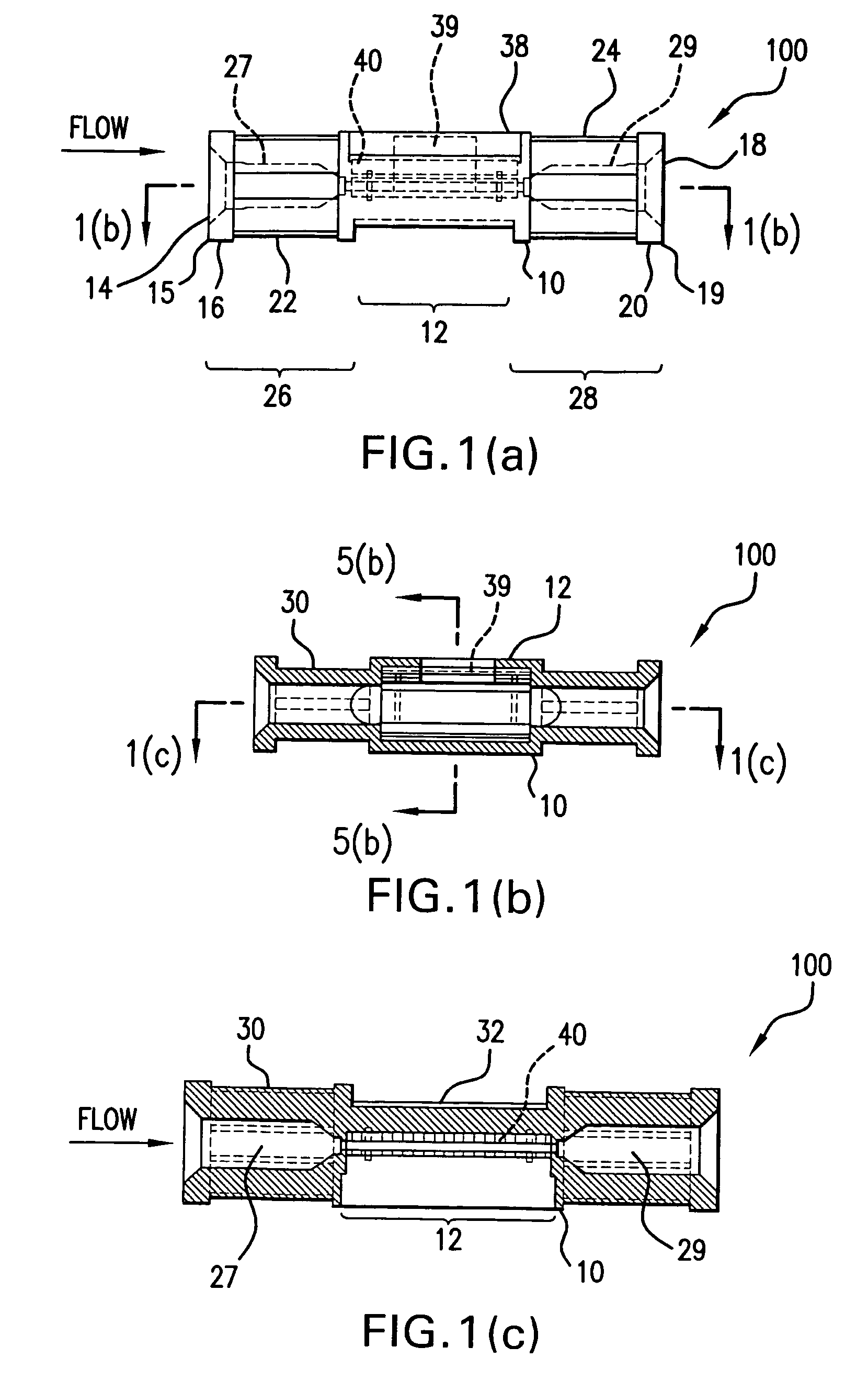
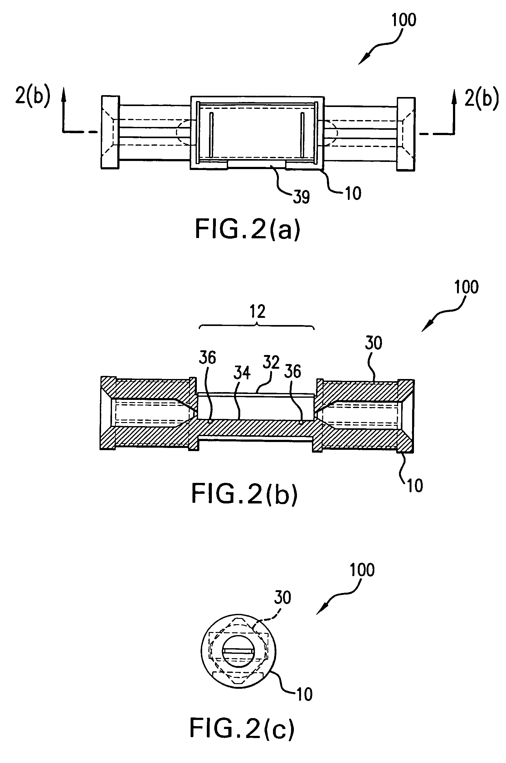
[0016]In accordance with another aspect of the invention, the housing can define a second fluid flow passage therethrough. The second fluid flow passage can be arranged for fluid communication in parallel with the first fluid flow passage between the upstream port and the downstream port. A valve can further be provided for selective flow through the second fluid flow passage. For example, the valve can be formed as a compressible wall member defining at least a portion of the second fluid flow passage. The compressible wall member can be formed from an elastomeric material. In a preferred embodiment, the second fluid flow passage has a first transverse dimension and a second transverse dimension perpendicular to the first transverse dimension. Preferably, the first dimension is smaller than the second dimension so as to be more readily compressible. Preferably, the cross section of the second fluid flow passage has an ellipsoidal shape with a small radius at each apex of the ellipse to facilitate compression of the second fluid flow passage.

Problems solved by technology

While methods for obtaining such information have existed for a long time, to date, no reliable low cost systems have been developed for disposable use.
For example, fluid flow measurements within a disposable IV fluid line or similar feed set generally have not been financially and technically viable up to this point in time.
Low cost electronic flow sensors have existed for some time, but have to date not presented a viable alternative for solving this problem.
Limitations to commercialization of such a device have included inadequate dynamic range of low-cost flow sensor systems and the unacceptable costs of total sensor assembly.
One problem with making flow sensors low cost is in the manufacturing process.
This configuration requires the manual step of welding wires from the chip to the lead frame, which can result in significant additional manufacturing costs.
The ultrasound approach may be subject to misalignment and other geometry changes that can impact the signal conduction around and through the fluid inside the tubing or other components of the disposable fluid path.
Also, the added cost of this air detection system is an impediment to its widespread adoption.

Method used


Image

  • Fluid flow measurement device
  • Fluid flow measurement device
  • Fluid flow measurement device

Examples


example i

Flow Measurement

[0104]As embodied herein, each capacitive pressure sensor 52, 56 is used to measure pressure by detecting the change in capacitance of the pressure sensor. This measurement is accomplished by applying a voltage across each pressure sensor 52, 56. A voltage signal is then generated that is indicative of the capacitance of the pressure sensor, and therefore indicative of the pressure in the flow at either upstream location 54 or downstream location 58 at a particular point in time. Signals obtained from each pressure sensor 52, 56 are routed to processor 110. FIG. 16 depicts signal levels over time from each pressure sensor. The upstream pressure sensor output is indicated by 151 and the downstream pressure sensor output is indicated by 152. As shown, the signal levels indicated by 151 and 152 are separated by a voltage level difference. The signal level difference, indicated by ΔV, is indicative of the pressure drop, and thus flowrate, between upstream location 54 and...

example ii

Air Detection

[0108]In accordance with another aspect of the invention, the determining step includes detecting the presence of air in the first fluid flow passage. The step of detecting air in the first fluid flow passage can include identifying convergence of the signal received from the upstream fluid pressure sensor and the signal received from the downstream fluid pressure sensor.

[0109]As embodied herein, the step of determining the presence of air in the first fluid flow passage 44 includes determining when the pressure difference measured by pressure sensors 52, 56 approaches zero.

[0110]FIGS. 16–17 depict a signal output for each pressure sensor 52, 56 when a 50 microliter bolus of air is being detected in first flow passage 44. The first signal trace 151 (in FIG. 16) and 156 (in FIG. 17) which is an expanded time scale of the same data is identified as above 0 units, and the second signal trace 158 is below zero units, wherein each unit can be a measure of voltage or of relat...

example iii

Pulsed Flow

[0113]In accordance with yet another aspect of the invention, a method is provided further including the steps of intermittently pulsing the fluid through the first fluid flow passage and detecting the fluid pressure in the first fluid flow passage using the upstream fluid pressure sensor and the downstream fluid pressure sensor to determine the amount of fluid delivered each time the pump is pulsed. This method of obtaining flow characteristics is particularly useful when the flow rate through the fluid flow system is sufficiently low, such that background noise will interfere with signal measurements of a continuous flow.

[0114]In accordance with this aspect of the invention, a data signal output (not shown) similar to that in FIG. 16 occurs, except that it indicates pulsed operation evidenced by each signal trace gaining amplitude, dropping to zero, and then repeating transient as expected with periodic flow. The area under the signal curve can be integrated and empiric...


PUM


Abstract

The invention is directed to a device for obtaining flow rate measurements including a sensor assembly and a housing. The sensor assembly includes a body defining a first fluid flow passage having an inlet, an outlet, a flow restricting element in the first fluid flow passage between the inlet and the outlet, an upstream fluid pressure sensor, a downstream fluid pressure sensor, an upstream signal contact connected to the upstream fluid pressure sensor, and a downstream signal contact connected to the downstream fluid pressure sensor. The housing has an upstream portion defining an upstream port, a downstream portion defining a downstream port, and a probe access port configured to provide access of a probe to at least one of the upstream signal contact and downstream signal contact. The housing can also define a second fluid flow passage in parallel with the first fluid flow passage. The device can be disposable.

Description

CROSS REFERENCE TO RELATED APPLICATION[0001]This application is a continuation of U.S. Ser. No. 10 / 442,575 filed on May 21, 2003 now U.S. Pat. No. 6,813,964.BACKGROUND OF THE INVENTION[0002]1. Field of the Invention[0003]The present invention relates to a flow sensor device to obtain flow characteristics of a fluid flow system, such as a system used in administering a beneficial agent to a patient. Particularly, the present invention is directed to a flow measurement device including first and second pressure sensors in a flow passage to measure a flow of beneficial agent and, optionally, the presence of air in the fluid flow system. The invention also includes a related system and method for obtaining such flow characteristics.[0004]2. Description of Related Art[0005]When administering a predetermined amount of a beneficial agent to a patient over an extended period of time in liquid form, it is beneficial, if not necessary, to obtain and monitor relevant flow characteristics such ...

Claims


Application Information

Patent Timeline
Patent Type & Authority Patents(United States)
IPC IPC(8): G01F1/00G01F1/34G01F1/37A61M5/168G01F1/36G01F1/38G01F1/40
CPCA61M5/16813A61M5/16854A61M5/16886G01F1/363G01F1/383G01F1/40
Inventor CLARK, GENE E.CHO, STEVE T.CHRISTIANSON, HARLOW B.SPERINDE, JOHN M.
Owner ICU MEDICAL INC
Learn More