Molded sprocket

a sprocket and molded technology, applied in the field of sprockets, can solve the problems of not being able to effectively drive the belt, being too abrasive in contact with the belt, and not being able to meet other needs, so as to achieve the effect of better addressing a given application

Inactive Publication Date: 2005-11-15
LAITRAM LLC
View PDF11 Cites 11 Cited by
  • Summary
  • Abstract
  • Description
  • Claims
  • Application Information

AI Technical Summary

Benefits of technology

[0003]These needs and others are satisfied by a sprocket embodying features of the invention. The sprocket comprises an exterior skin and an integrally molded interior core. The skin is molded of a first plastic material, and the core is molded of a second plastic material. In this way, the sprocket can combine the advantageous properties of both materials to better address a given application.

Problems solved by technology

In some instances, the properties of a single material may serve some of the needs of an application well, but may be less than optimum for other needs.
For example, in an abrasive environment, a sprocket made entirely of polyurethane, which has good abrasion-resistant properties, may be suggested, but it may be too flexible to drive the belt effectively.
As another example, glass-filled materials provide strength and firmness to plastic articles, but are too abrasive in contact with a belt.

Method used


Image

  • Molded sprocket
  • Molded sprocket
  • Molded sprocket

Examples


Embodiment Construction

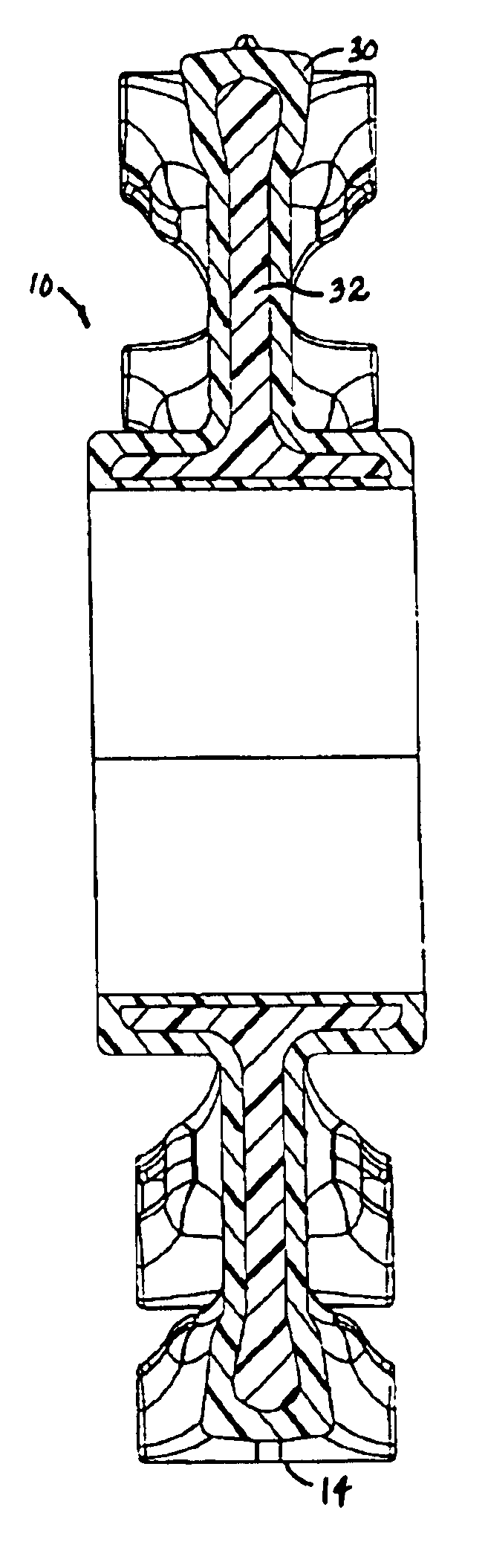
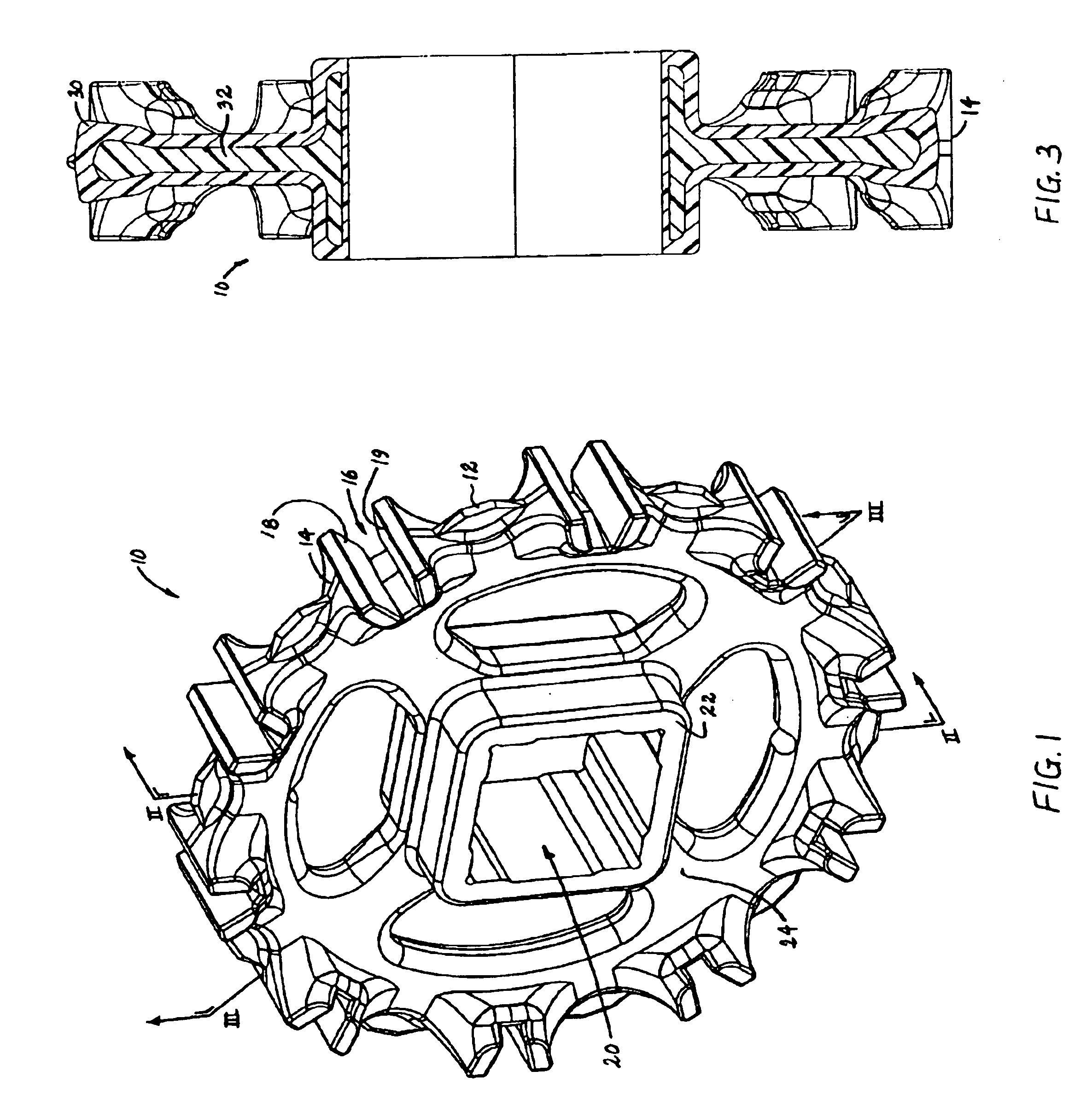
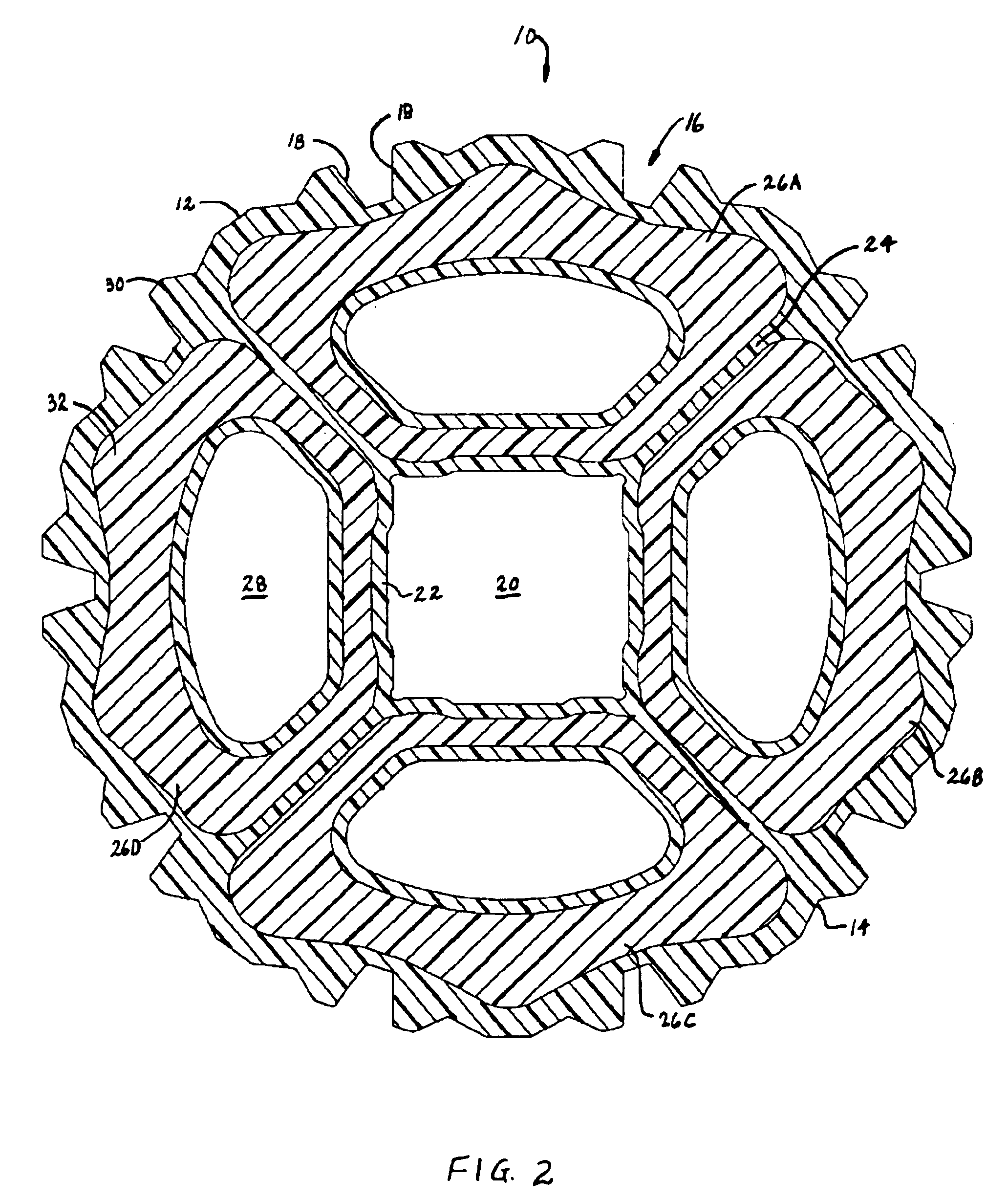
[0010]An exemplary sprocket embodying features of the invention is shown in FIGS. 1-3. The shape of the sprocket 10 is the same as that of an INTRALOX Series 800 sprocket manufactured and sold by Intralox, Inc. of Harahan, La., USA. Ten tracking teeth 12 are spaced around the circumferential periphery 14 of the sprocket. Midway between consecutive tracking teeth are grooves 16 with leading and trailing driving surfaces 18, 19 for engaging complementary drive surfaces on a modular plastic conveyor belt. The sprocket also forms a central axial bore 20, shown as generally square to receive a square shaft. A hub 22 around the bore extends axially in the width direction of the sprocket farther than the other parts of the sprocket. Spokes 24 extend from the hub to the outer periphery and divide the sprocket into four regions 26A-D. An opening 28 formed in each region makes the sprocket easy to clean and lighter in weight.

[0011]As illustrated in the cross sections of FIGS. 2 and 3, the spr...


PUM

PropertyMeasurementUnit
thickaaaaaaaaaa
electrically conductiveaaaaaaaaaa
plasticaaaaaaaaaa

Abstract

A two-material plastic sprocket for modular plastic conveyor belts and an associated method for molding such a sprocket. The sprocket is made of a first plastic material forming the exterior skin and a second plastic material forming the interior core. The sprocket is preferably molded in a co-injection molding process.

Description

BACKGROUND OF INVENTION[0001]The invention relates generally to sprockets used to drive modular plastic conveyor belts and, more particularly, to sprockets molded out of two plastic materials.[0002]Modular plastic conveyor belts are used in a wide range of conveyor applications. Unlike flat belts, which are driven by tensioned rollers or pulleys, modular plastic conveyor belts are driven by sprockets, which positively engage drive structure in the belts. The most common sprockets are molded or machined out of one homogeneous plastic or metal material. The sprocket material is chosen to best match the application. In some instances, the properties of a single material may serve some of the needs of an application well, but may be less than optimum for other needs. For example, in an abrasive environment, a sprocket made entirely of polyurethane, which has good abrasion-resistant properties, may be suggested, but it may be too flexible to drive the belt effectively. As another example...

Claims


Application Information

Patent Timeline
Patent Type & Authority Patents(United States)
IPC IPC(8): B29C45/16F16H55/30F16H55/02F16H55/06
CPCB29C45/1642F16H55/06F16H55/30
Inventor VERDIGETS, CHRISTOPHER J.SOFRANEC, RICHARD J.
Owner LAITRAM LLC
Why Eureka
Try Eureka