Vehicle door handle device

a technology for vehicle doors and handles, applied in the field of door handles, can solve the problems of increasing the number of parts, generating a chattering noise relative to the frame, and relatively complex structure, and achieve the effect of inhibiting the dislocation of the handgrip

Inactive Publication Date: 2005-11-15
AISIN SEIKI KK
View PDF18 Cites 28 Cited by
  • Summary
  • Abstract
  • Description
  • Claims
  • Application Information

AI Technical Summary

Benefits of technology

[0006]According to one aspect, a vehicle door handle device includes a frame equipped on the door panel of a vehicle door, and a handgrip having a first end portion rotatably mounted on the frame and a second end portion forming an operation portion linked with a door lock mechanism. The handgrip is rotatable within a predetermined angle to operate the door lock mechanism and effect opening of the vehicle door when the operation portion of the handgrip is moved to rotate the handgrip relative to the frame. A projection is formed on one of the frame and the first end portion of the handgrip, while a groove is formed on the other of the frame and the first end portion of the handgrip. The projection is positioned in the groove to move within the groove when the operation portion of the handgrip is moved to rotate the handgrip relative to the frame. The projection is also engageable with a periphery of the groove to inhibit dislocation of the handgrip from the frame.

Problems solved by technology

However, because the lock mechanism is required in addition to the frame and the handgrip in order to restrict the movement of the handgrip, the number of parts is increased and the structure is relatively complicated.
Further, by virtue of assembly errors with respect to assembling the lock mechanism to the frame, the handgrip may have excessive play and may thus generate a chattering noise relative to the frame.

Method used


Image

  • Vehicle door handle device
  • Vehicle door handle device
  • Vehicle door handle device

Examples


Embodiment Construction

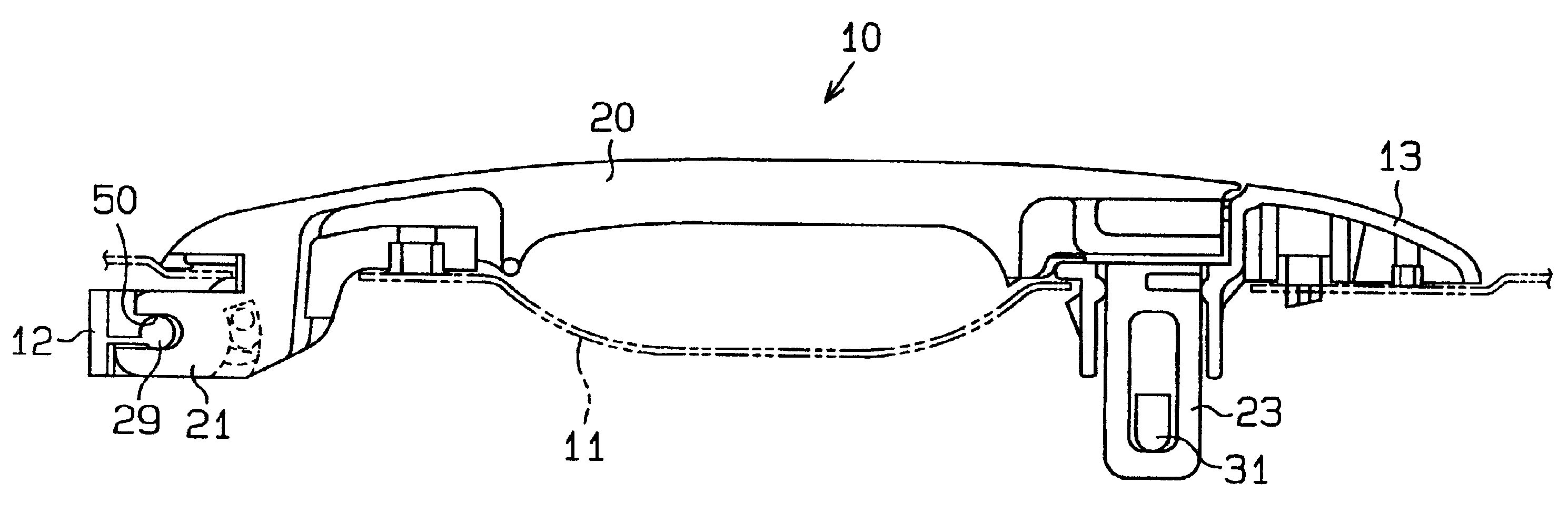
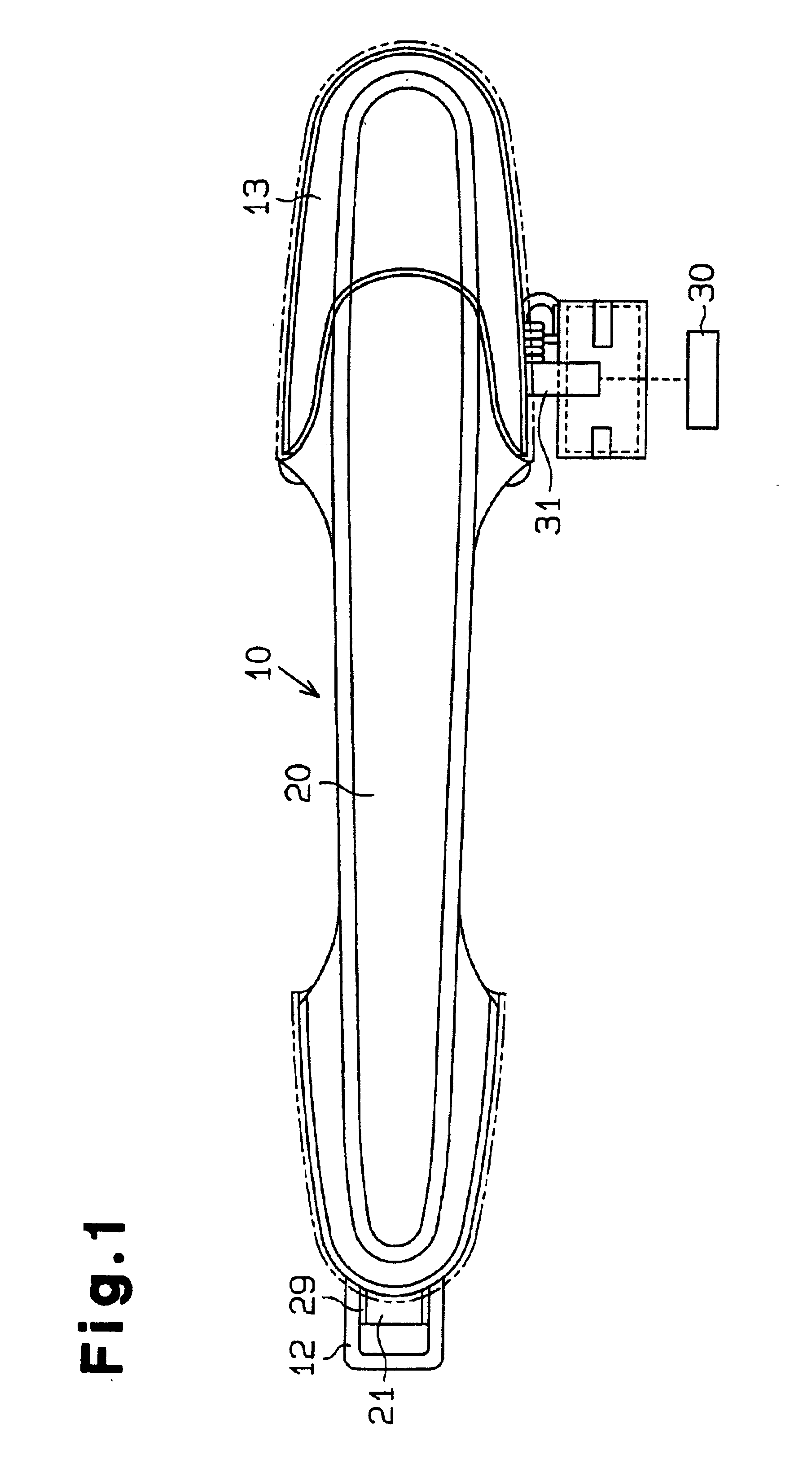
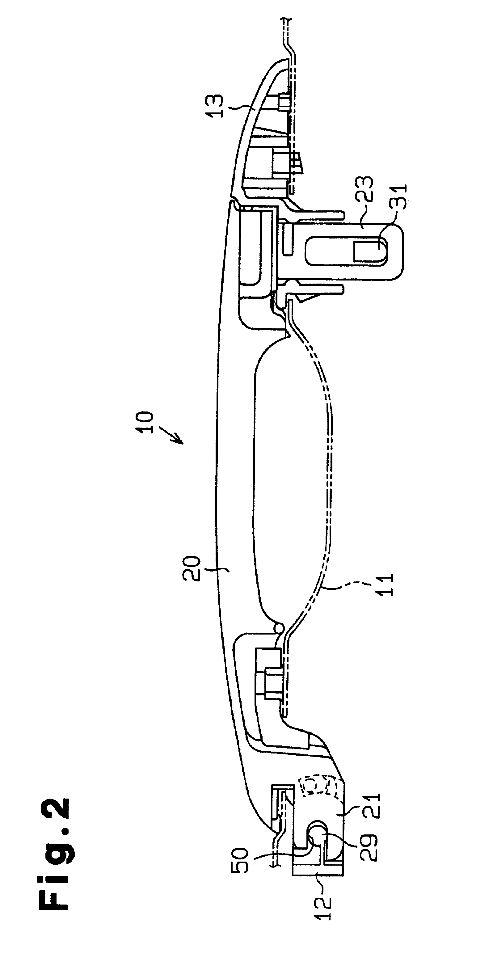
[0021]As shown in FIGS. 1 and 2, one embodiment of a vehicle door handle device 10 includes a frame equipped on the door panel 11 of a vehicle door and an elongated handgrip 20. The frame includes a first base member 12 mounted on the vehicle door panel 11 and a second base member 13 mounted on the vehicle door panel 11. The first and second base members 12, 13 are separate from one another and are mounted on the vehicle door panel 11 to maintain a predetermined distance between the two base members 12, 13 in the longitudinal direction of the vehicle (i.e., the right to left direction in FIG. 1). The elongated handgrip 20 extends in the longitudinal direction of the vehicle approximately parallel with the vehicle door panel 11. One end portion of the handgrip 20 (i.e., a first end portion) is operatively connected to the first base member 12 and the other end portion of the handgrip 20 (i.e., a second end portion) is operatively connected to the second base member 13.

[0022]The first...


PUM


Abstract

A vehicle door handle device includes a frame equipped on a vehicle door panel and a handgrip mounted on the frame and rotatable about a rotation center portion at one end portion of the handgrip. A second end portion of the handgrip forms an operation portion linked with a door lock mechanism. The handgrip is adapted to be rotated within a predetermined angle around the rotation center portion to operate the door lock mechanism when the operation portion is pulled away from the frame. A restriction mechanism is also provided to restrict chattering and / or dislocation of the handgrip from the frame. The restriction mechanism includes a projection and a groove provided between the frame and the handgrip. The projection is slidable in the groove during rotation of the handgrip and is able to contact a boundary of the groove in the inserting direction of the handgrip.

Description

[0001]This application is based on and claims priority under 35 U.S.C. §119 with respect to Japanese Application No. 2001-004020 filed on Jan. 11, 2001 and Japanese Application No. 2001-022566 filed on Jan. 31, 2001, the entire content of both of which is incorporated herein by reference.FIELD OF THE INVENTION[0002]This invention generally relates to a door handle. More particularly, the present invention pertains to a vehicle door handle device having a grip type outside door handle.BACKGROUND OF THE INVENTION[0003]Japanese Utility Model Publication No. H06-7188 discloses a known vehicle door handle device. This known vehicle door handle device includes a handgrip having a rotation center rotatably fitted into a frame on one end portion and a lock mechanism contacting the one end portion in the direction for inserting the handgrip into the frame. The movement of the handgrip in the inserting direction into the frame is restricted by the lock mechanism. Accordingly, the lock mechani...

Claims


Application Information

Patent Timeline
Patent Type & Authority Patents(United States)
IPC IPC(8): E05B65/20E05B17/00
CPCE05B85/16E05B77/36Y10S292/12Y10T16/458Y10S292/64Y10T292/79Y10T292/57Y10T292/82
Inventor NOMURA, MORIHITOOOE, KOUJINAGATA, KOUICHIKAMIYA, ATSUSHISUZUKI, YOSHIMASA
Owner AISIN SEIKI KK
Why Eureka
Try Eureka