
High performance, high capacitance gain, jack connector for data transmission or the like

a high capacitance gain, data transmission technology, applied in the direction of contact members penetrating/cutting insulation/cable strands, line/current collector details, coupling device connections, etc., can solve the problem of limited durability and reliability, difficult and costly implementation, and increased crosstalk. problem, to achieve the effect of high-performance data transfer and enhanced crosstalk reduction during data transfer

Inactive Publication Date: 2005-11-15
BEL FUSE MACAO COMML OFFSHORE
View PDF48 Cites 47 Cited by
  • Summary
  • Abstract
  • Description
  • Claims
  • Application Information

AI Technical Summary

Benefits of technology

This configuration effectively reduces crosstalk, ensuring optimal data transfer at high frequencies with increased transmission speeds without signal degradation, while being simple, economical, and durable.

Problems solved by technology

As the frequency of interfering signals due to crosstalk and associated error rate increases, namely, during high performance communications, crosstalk becomes increasingly significant, often interfering with and otherwise obstructing data transfer.
Although prior attempts at crosstalk reduction have met with some success, they have been found not only difficult and costly to implement, but also of limited durability and reliability.

Method used


Image

  • High performance, high capacitance gain, jack connector for data transmission or the like
  • High performance, high capacitance gain, jack connector for data transmission or the like
  • High performance, high capacitance gain, jack connector for data transmission or the like

Examples


example

[0092]To achieve a selected capacitance, in accordance with the present invention, extension plates are used where x=100 mils, y=140 mils and s=17 mils. The plate-like extensions are positioned generally parallel to one another and a Valox® 553 insert is located in the space between them, this material having a relative dielectric constant, ∈r, of about 3.7. Using the above formula, c=22.49e−5 (((3.7)(100)(140) / (17)), the plate capacitance is calculated to be 0.685 pf.

[0093]Although the present invention has been shown and described as utilizing a conventional conductive material for the contacts, such as commercially pure copper, it is understood that operative components of this invention may be constructed of other high conductivity materials, giving consideration to the purpose for which the present invention is intended. For example, a copper alloy, silver and / or alloys thereof, aluminum and / or its alloys, fiber optic materials, and super conductors or the like may also be used...


PUM


Abstract

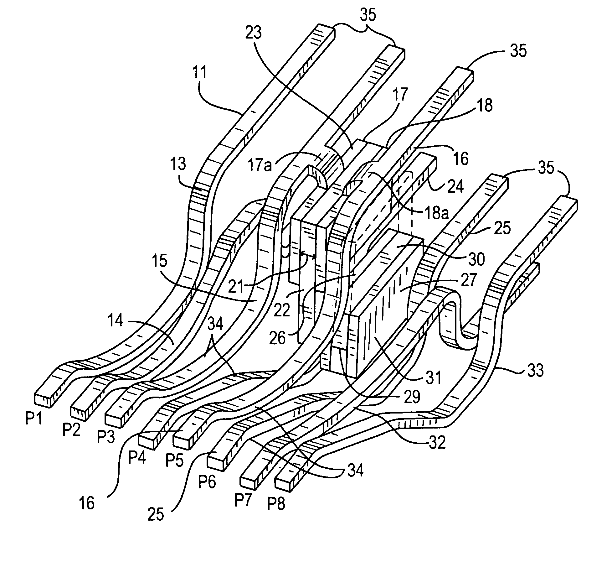
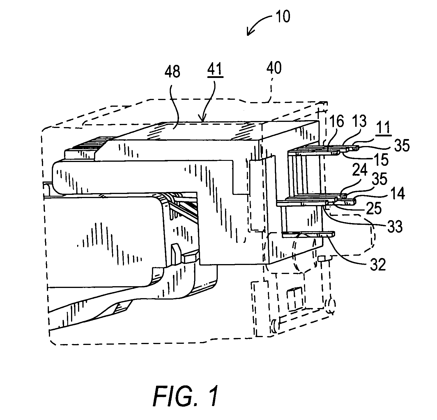
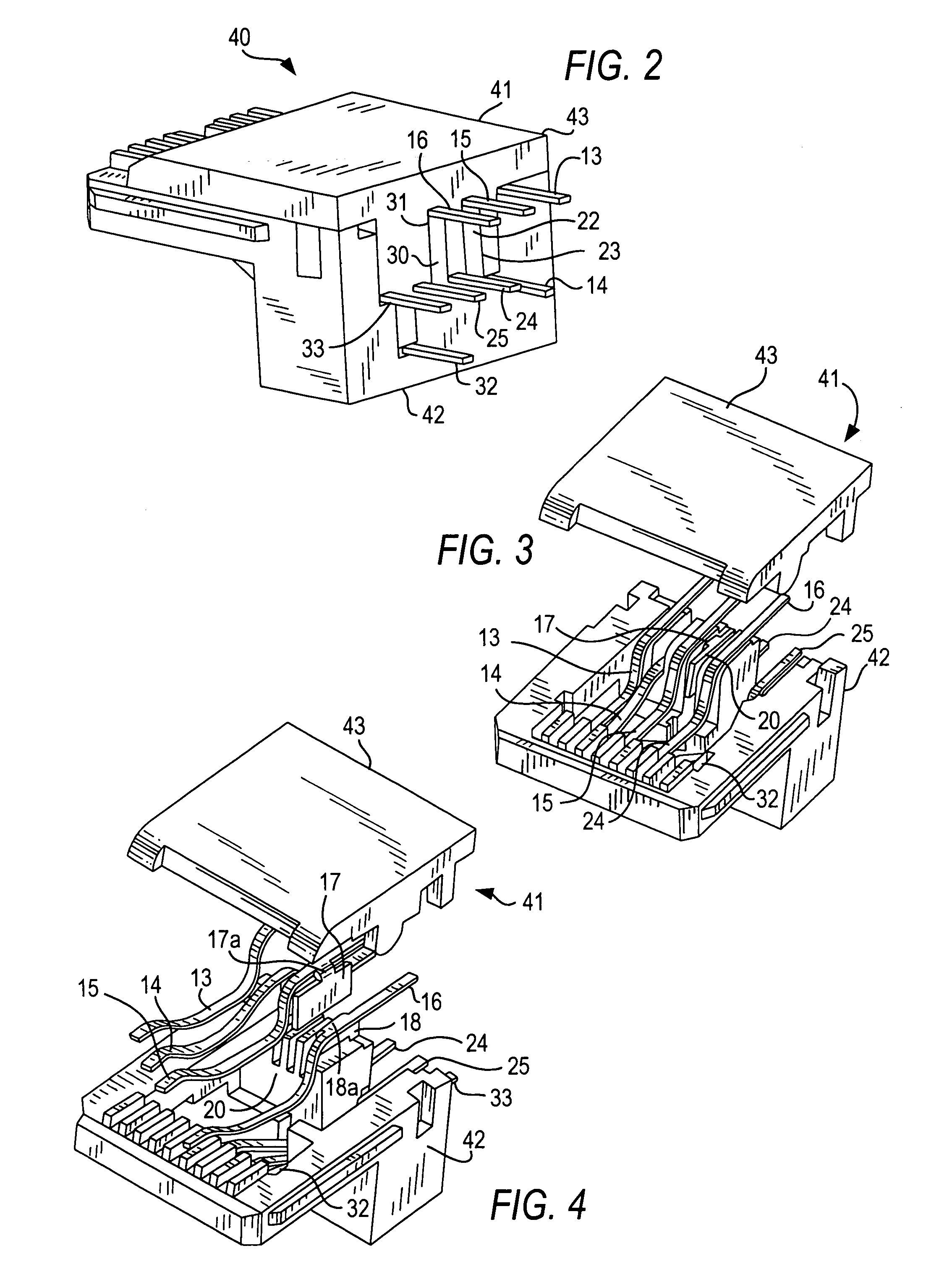
A high performance, high capacitance gain, electric connector for data transfer applications. At least eight sequentially positioned elongate contact members are connected in a series of signal pairs. A first signal pair includes a fourth contact member and a fifth contact member. A second signal pair includes a third contact member and a sixth contact member. In addition, a third signal pair comprises a first contact member and a second contact member. Finally, a seventh and an eighth contact member are in a fourth signal pair. One member of each contact member pair is configured differently from the other member of the pair, the respective contact members being oriented relative to one another such that they substantially remain in generally parallel planes, but define non-parallel paths. Each of the third and fifth contact members mounts a plate-like extension oriented in a first direction and in respective planes generally parallel to one another. Each pair of extensions are separated by a first dielectric such that a first capacitor is formed. Furthermore, each of the fourth and sixth contact members mounts a plate-like extension oriented in a second direction and also in respective planes generally parallel to one another. Each pair of extensions are likewise separated by a second dielectric such that a second capacitor is formed. Each contact of each contact member pair has a plug engaging portion and a board engaging portion, the plurality of contact members having a selected shape, being arranged relative to one another, and being housed collectively by a dielectric casing so as to minimize crosstalk during data transfer.

Description

BACKGROUND OF THE INVENTION[0001]The present invention relates generally to electric connectors and, more particularly, to an interference inhibiting, electric connector for use in high frequency data communications or the like.[0002]Conventional jack connectors for data communications are characterized by a dielectric housing with a series of contacts positioned within the housing in relatively close proximity to one another. The jack contacts establish electrical connection between a corresponding wire conductor at one end of the contact and plug contacts and circuits on a printed circuit board on which the jack is mounted.[0003]In locating the contacts in relative proximity to one another, especially during high performance communications, the contacts themselves become antennae for both broadcasting and receiving electromagnetic radiation. This leads to signal coupling between different pairs of contacts, a phenomenon commonly known as crosstalk. Crosstalk is a source of interfe...

Claims


Application Information

Patent Timeline
Patent Type & Authority Patents(United States)
IPC IPC(8): H01R13/00H01R24/04H01R43/00H01R13/646H01R4/24H01R24/00H01R3/00H01RH01R13/66H01R24/58
CPCH01R24/64H01R13/6464H01R13/6625Y10S439/941
Inventor COLANTUONO, ROBERT G.MAROWSKY, RICHARD D.COWBURN, JASON A.BUSH, DENNIS A.
Owner BEL FUSE MACAO COMML OFFSHORE
Learn More