Back brace

a back brace and bracing technology, applied in the field of back braces, can solve the problems of increasing the number of muscular and orthopedic problems in the human patient, the pain of the back brace, and the cost of work, so as to increase the flexibility at the edge, and reduce the pain of the back bra

a back brace and bracing technology, applied in the field of back braces, can solve the problems of increasing the number of muscular and orthopedic problems in the human patient, the pain of the back brace, and the cost of work, so as to increase the flexibility at the edge, and reduce the pain of the back bra

US6964644B1Inactive Publication Date: 2005-11-15W G HLDG

Image

  • Back brace
  • Back brace
  • Back brace

Examples


Embodiment Construction

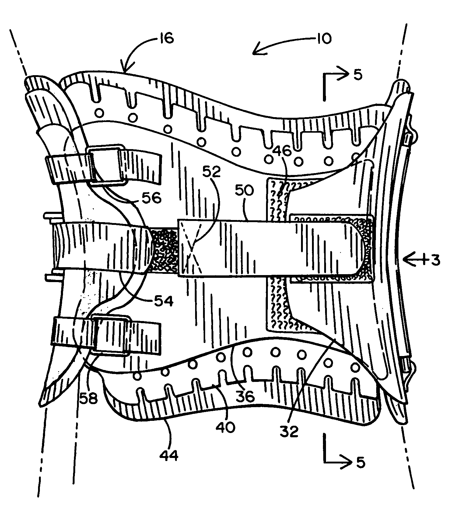
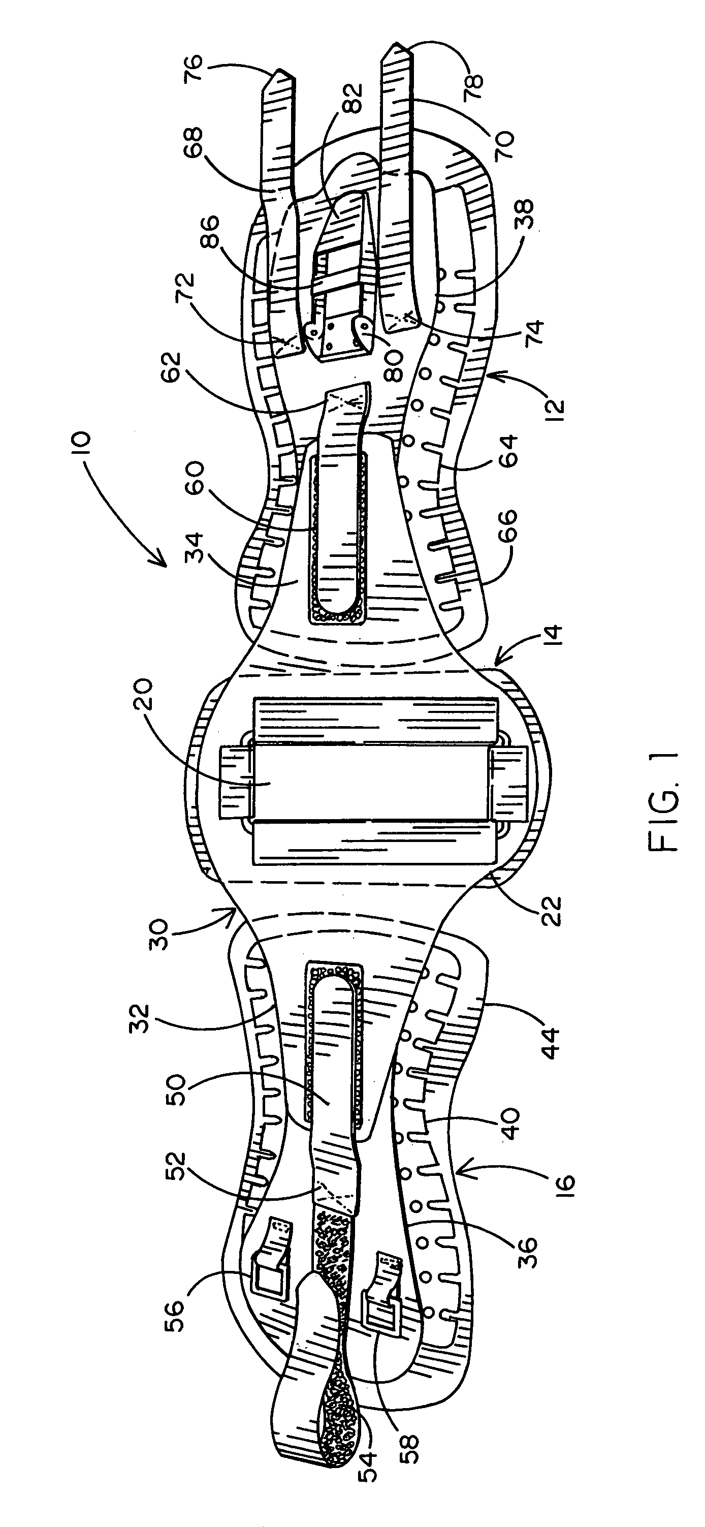
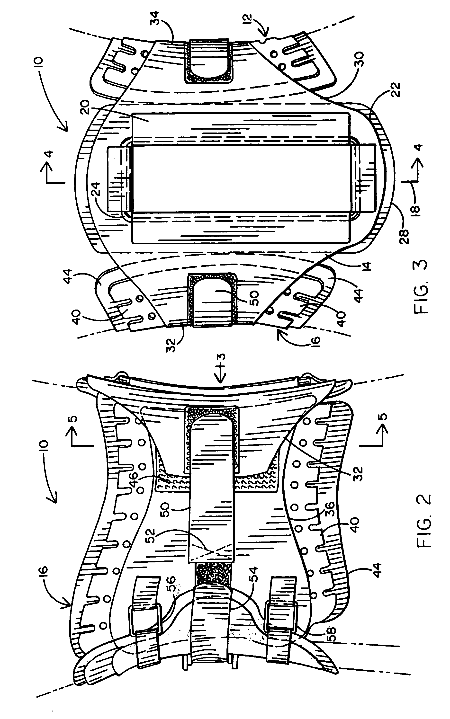
[0030]The first preferred embodiment of the back brace of this invention is generally indicated by the numeral 10 and is shown in a spread-out view in FIG. 1, is shown in left side elevation in FIG. 2, is shown in rear elevation in FIG. 3, and is shown in front elevation in FIG. 9. The back brace 10 comprises three panels which overlap with respect to each other when worn. These three panels comprise the right panel 12, back panel 14 and left panel 16. The back panel 14 has a center line 18, which is the section line upon which FIG. 4 is taken (see FIG. 3). When worn, the center line should overlie the patient's spine. The main body of the back panel is formed of flexible sheet synthetic polymer composition material which bends, but is not appreciably stretchy.

[0031]Window 20 is formed along the center line. The window extends upward from close to the bottom edge 22, which overlies the sacrum when worn. Attached to the back panel 14 around the window 20 is malleable bar 24. The mall...


PUM


Abstract

A back brace has left, right and back panels that substantially overlap to form a tubular back brace when worn. Leverage multiples tightening force during tightening. After each successive tightening by the lever, retaining bands retain the back brace in position. Pressure spreading layers have a secondary adjustment mechanism comprising a plurality of notches extending inward from upper and lower edges, and at least one hole aligned with each of the plurality of notches. The back panel has a window overlying the sacrum. The orthopedist can observe the engagement of the back brace in this area through the window. A malleable bar is attached to the back panel adjacent the window so that the orthopedist can adjust the malleable bar for proper fit. After the initial fitting, including adjustment of the back panel over the sacrum, the back brace may be readily donned and doffed by the patient.

Description

CROSS-REFERENCE[0001]This application is a continuation-in-part of my previous application Ser. No. 09 / 323,291, filed Jun. 1, 1999 (now abandoned), and is a continuation of my previously filed application Ser. No. 09 / 785,597 filed Feb. 16, 2001, now abandoned for β€œBack Brace”, the entire disclosures of which are incorporated herein by this reference.FIELD OF THE INVENTION[0002]This invention is directed to a back brace which surrounds the mid-torso of the patient with three overlapping panels secured to each other to form a tubular back brace. The tubular back brace has a window in the back panel with an adjacent malleable frame which can be bent to conform to the patient. A single lever step-by-step tightening structure permits the patient to achieve easily adequate circumferential tension when he redons the back brace after an initial fitting.BACKGROUND OF THE INVENTION[0003]A number of muscular and orthopedic problems are present in the human patient above the sacrum. There are a...

Claims


Application Information

Patent Timeline
15 Nov 2005
Publication
US6964644B1
IPC
A61F5/00; A61F5/02
CPC
A61F5/028
Inventors
GARTH, GEOFFREY C.