

Image processing circuit and method for processing image
- Summary
- Abstract
- Description
- Claims
- Application Information
AI Technical Summary
Benefits of technology
Problems solved by technology
Method used
Image

Examples
first embodiment
[0036](1) Configuration of First Embodiment
[0037](1-1) Whole Configuration of First Embodiment
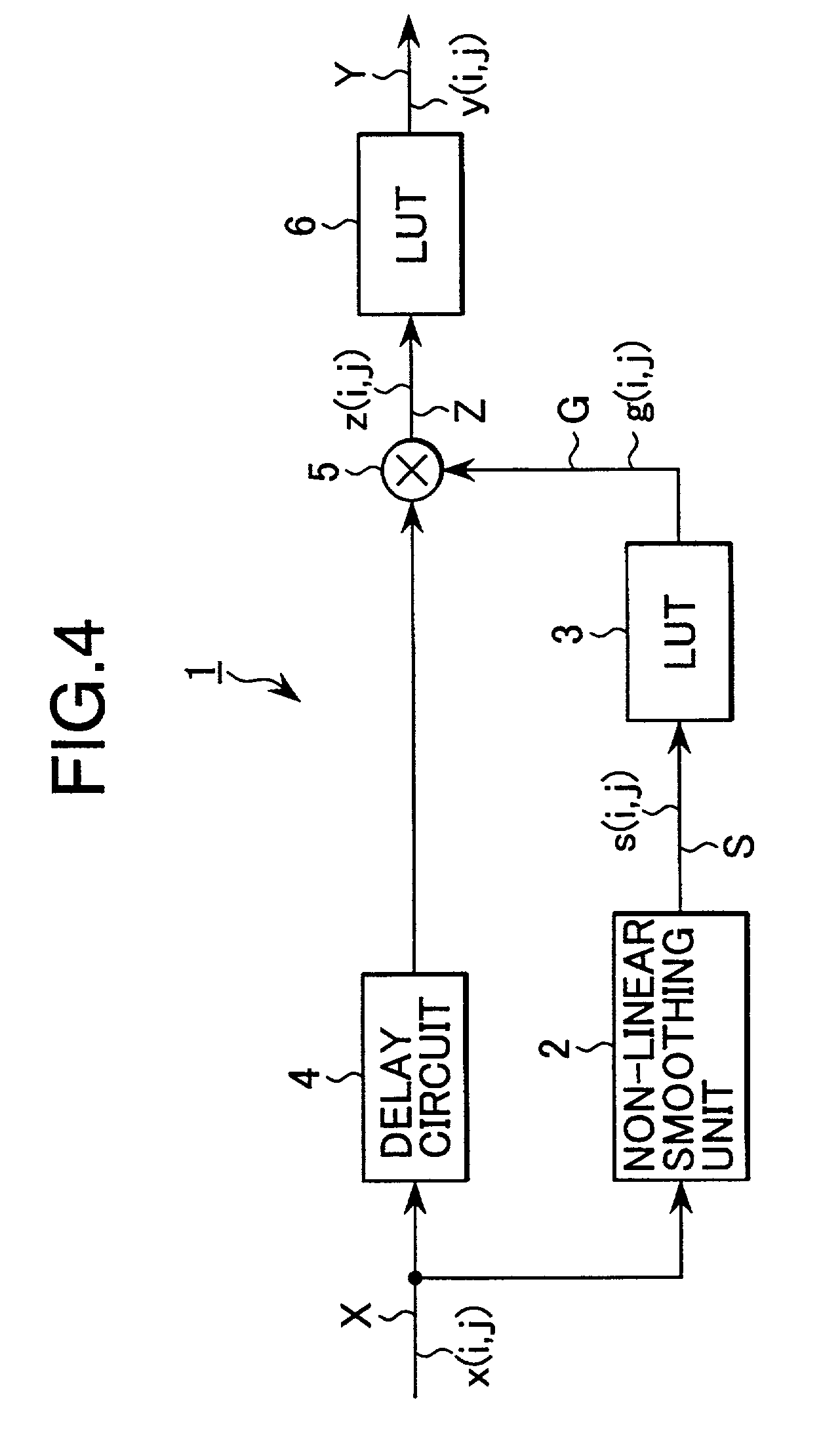
[0038]FIG. 4 is a block diagram showing an image processing circuit according to the first embodiment of the present invention. The present image processing circuit 1 is applied to an imaging apparatus such as a video camera and a digital camera, various image processing apparatus, image transmission apparatus, the image processing in a personal computer, and the like for compressing the dynamic range of an input image X to output an output image Y.
[0039]Incidentally, here, the input image X and the output image Y are two-dimensional digital images. Hereinafter, positions of a pixel in the horizontal direction and the vertical direction are designated by marks “i” and “j”, respectively, and the pixel values of the input image X and the output image Y are designated by x(i, j) and y(i, j), respectively. Moreover, respective processed values corresponding to the pixel values x(i, j) and y(i, ...
second embodiment
[0112](4) Second Embodiment
[0113]FIG. 15 is a block diagram showing an image processing circuit according to a second embodiment of the present invention in comparison with the first embodiment shown in FIG. 4. In the image processing circuit 41, the identical constitutional components to those of the image processing circuit 1 are designated by corresponding marks, and the overlapping description of them is omitted.
[0114]The image processing circuit 41, like the image processing circuit 1, as shown in FIGS. 16A–16F, smoothes the input image X (FIG. 16A) constituted of the pixel value x(i, j) to generate a smoothed image S (FIG. 16B), and compress the dynamic range of the input image X by the gain correction coefficient g(i, j) (FIG. 16C) generated by the pixel value s(i, j) of the smoothed image S. In the processing, the image processing circuit 41 emphasizes the variations of the pixel value y(i, j) of the output image Y by using the subtraction value x(i, j)−s(i, j) which is obta...
third embodiment
[0117](5) Third Embodiment
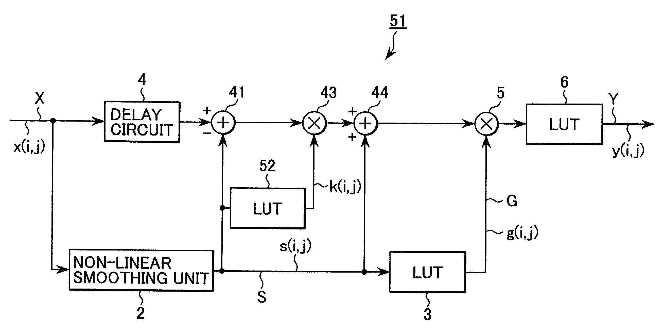
[0118]FIG. 17 is a block diagram showing an image processing circuit 51 in accordance with a third embodiment of the present invention in comparison with the embodiment shown in FIG. 15. In the image processing circuit 51, the identical constitutional components to those of the image processing circuit 41 are designated by reference marks corresponding to those of the image processing circuit 41, and the overlapping description is omitted.
[0119]The image processing circuit 51 sets the gain of the multiplier 43 by accessing a look-up table 52 by the output value s(i, j) of the smoothed image S. Here, the input-output characteristic of the look-up table 52 is set as shown in FIG. 18. Hereby, the look-up table 52 sets the gain of the multiplier 43 at a constant gain when the output value s(i, j) is equal to a prescribed value or less, and sets the gain so as to approach gradually to the value one when the output value s(i, j) increases to be equal to the presc...
PUM
 Abstract
Description
Claims
Application Information